I am trying to join the Aleph-X builders club. I have successfully constructed one block.
I have 4 output IRFP044 FETs, 24Vrails and 2A bias.
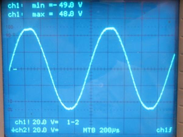
Here is the differential output signal with no load (just the 34 ohms to ground per output.)
I have intentionally driven it to clipping. As you can see I have about 96V peak to peak.
Here is the same scenario with scope probes referenced to ground.
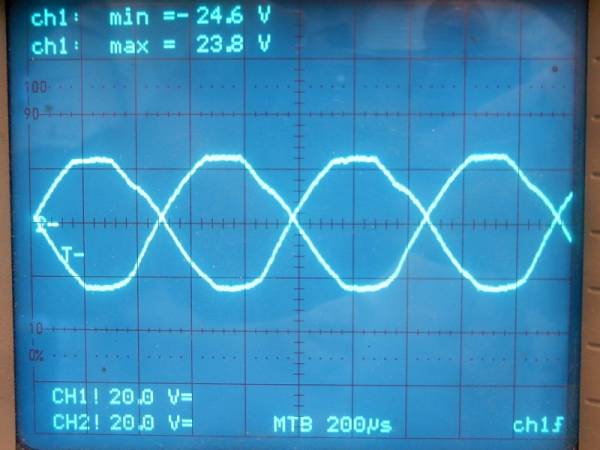
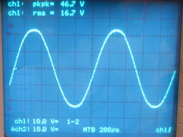
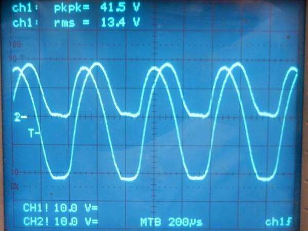
Now here is the differntial output signal into a 7ohm load, only about 46Vpk-pk.
Into 7ohm load with scope probes referenced to ground.
Do these waveforms look normal?
I would obviously like to have more output voltage into a load, is there something wrong with my circuit?
Would increasing my number of output FETs from 4 to 8 give me more output voltage?
I have 4 output IRFP044 FETs, 24Vrails and 2A bias.
Here is the differential output signal with no load (just the 34 ohms to ground per output.)
I have intentionally driven it to clipping. As you can see I have about 96V peak to peak.
Here is the same scenario with scope probes referenced to ground.
Now here is the differntial output signal into a 7ohm load, only about 46Vpk-pk.
Into 7ohm load with scope probes referenced to ground.
Do these waveforms look normal?
I would obviously like to have more output voltage into a load, is there something wrong with my circuit?
Would increasing my number of output FETs from 4 to 8 give me more output voltage?
Pass DIY Addict
Joined 2000
Paid Member
Waveforms look OK, but something doesn't seem right to me with your numbers. 24V rails with 2A bias (total) yields less than 20w into an 8ohm load. Unless you mean 2A bias PER SIDE, or 4A total, then you should see about 60w into an 8ohm load and close to 30w into a 4ohm load. At this level, each FET is burning near 50w which is a bit high - 20-30w per fet is the typical target range.
Provided neither is a "starvation situation" your mix of rail voltage & bias current typically follow the pattern of:
-More output power into an 8 ohm load = higher rail voltage
-More output power into a 4 ohm (or lower) load = higher bias current
Bias current and rail voltage interact to large extent in the Aleph-X amps.
What is your output wattage goal and are you looking to drive 4ohm or 8ohm speakers?
Oops, my miscommunication. I do mean 2A per side for 4A total. I'm also at about 58% AC current gain.
I am only getting 35W into my 7ohm load... 7*(16Vrms)^2.
My power supply is adequate, so I'm not worried about that. Each rail has a 400VA xfmr and 0.16F capacitance.
Yeah I know i'm running my FETs a lot hotter than recommended. Its one of the things I am "experimenting" with in this project.
I'll likely end up using 8ohm speakers.
Pass DIY Addict
Joined 2000
Paid Member
Glad you found my web page helpful - that's half the reason I created it. The other half is it was my own running set of notes over the years it took for me to get my own amps built and running.
I think something is incorrect in your calculations/measurement. Your 3rd scope trace indicates you are swinging 46vp-p into a 7ohm load with 24v rails - this sounds too high of an output voltage given your rail voltage, unless you are well into distortion/clipping already.
Are you sure you have connected your probes properly? Have a look at the output measurement section of my web page.
P-P v swing = RMS voltage swing * sqrt(2)
Output wattage = (p2p^2 ) / Load * 2
You should be seeing more than 35w out of your current set up - my guess is something closer to 60-70...
Pass DIY Addict
Joined 2000
Paid Member
Hmmm... I posted too quickly. Your math seems to check out. This makes me think something is not right with your measurement technique. Grey's original design had 15v rails, 4.5A bias, and produced about 38w into both 8ohms and 4ohms.
Given that your rails are much higher and bias is only slightly lower (not to mention higher AC current gain), you should be seeing way more than 35w... Measurement technique is the easiest part to check before you go tearing into the your build.
Given that your rails are much higher and bias is only slightly lower (not to mention higher AC current gain), you should be seeing way more than 35w... Measurement technique is the easiest part to check before you go tearing into the your build.
Thanks for the replies. The signal is indeed clipping in all 4 of my pictures.
Yes, it does seem that my scope is measuring a bit high.
After some reading, I found the formula I used for power is wrong. The formula I used was
P = [(Vrms)^2]/R
The formula you mentioned Eric is the correct one.
P = [(Vpp)^2]/2R
With this proper formula, my amp is putting out more like
P = [(40Vpp)^2]/[(7ohm)(2)] = 110W
Pass DIY Addict
Joined 2000
Paid Member
That output measurement sounds a bit better... At this point, I don't see where you would need more power into a 7ohm load.
I know that the 044's can handle more heat and more current than the 240's, but you want to consider doubling up your output mosfets for greater longevity. Have a look at the datasheets and the Safe Operating Area for the voltage and current level you are using, and derate their current capability according to your temperature measurements. I don't remember the specifics, but it seems to that you should be running your output mosfets at less than 50% of their maximum SOA...
I know that the 044's can handle more heat and more current than the 240's, but you want to consider doubling up your output mosfets for greater longevity. Have a look at the datasheets and the Safe Operating Area for the voltage and current level you are using, and derate their current capability according to your temperature measurements. I don't remember the specifics, but it seems to that you should be running your output mosfets at less than 50% of their maximum SOA...
Funny thing, the word “need” 
Yeah, I know I'm pushing my FETs hard, but I’m making a hot rod here lol...
I couldn’t find where I read this, but somewhere I read that the temp you run the FET at + the max power you run the FET at should be less than the FET’s max rated power.
So, for my 120W 044’s if I run them at 50W I have to keep them below 70 degrees C.
Anyway, you are right. Doubling the FETs would be the "responsible" thing to do. I’ll try it and see how it goes. Should get me more power into 4 ohms, which is something I "need"
Pass DIY Addict
Joined 2000
Paid Member
Hmmm.. if you don't increase your bias current, you just might be OK for the long run.
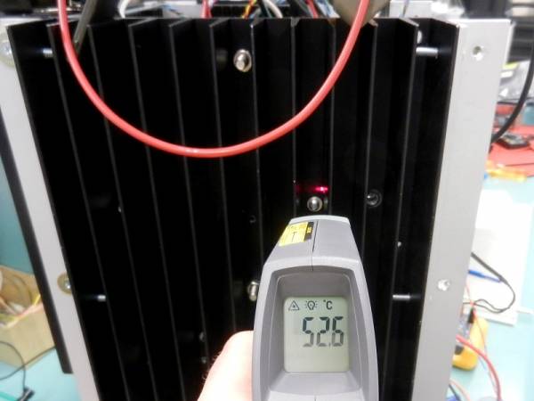
According to the IRFP044 datasheet, the device is rated for 180w max power dissipation. This figure has a linear derating factor of 1.2w/c above a case temperature of 25c. Give the heatsink temperature of 52c that you show in your first image, lets assume that the case temperature of your mosfets are closer to 65c (they are probably a little cooler than this, but let's be conservative). This is 40c above 25c, so we derate by 40*1.2 or 48w. Thus, at Tc of 65c, maximum power dissipation = 180w - 48w or 130w (again, rounding to be conservative in approach).
So, at a level that is higher than your measured temperature (assuming reasonably good technique for mounting your fets to the sink), you should be able to dissipate 130w from each mosfet. Given your rail voltage and bias current, it looks like you are pulling about 50w from each mosfet. Thus, you are running at about 38% of the maximum output at this temperature.
You just might be fine leaving things the way they are...
Having said that, you are likely to experience longer device life at a lower temperature and doubling your output devices just seems like a "kind" thing to do...
If you do increase your bias level, though, more mosfets is just about mandatory...
I have been losing sleep over power calculations...
Here is the correct power formula for continous power of a sinusoidal waveform into a purely resistive load.
P = [(Vrms)^2]/R
So a 40V peak to peak sine wave into an 8 ohm resistor results in
P = [(14.142V)^2]/8ohm = 25W
This formula gives the same result
P = [(Vpeak)^2]/2R
Which would be [(20V)^2]/(2*8ohm) = 25W
So my 16Vrms signal into my 7 ohm resistor is
[(16)^2]/7 = 36.6W
Pass DIY Addict
Joined 2000
Paid Member
I have been losing sleep over power calculations...
Ha - welcome to DIY Class-A biasing for your first amp
Here is the correct power formula for continous power of a sinusoidal waveform into a purely resistive load.
P = [(Vrms)^2]/R
OK, this formula matches/confirms my own output power readings for my amps as well as William's AXE spreadsheet (linked on my Aleph-X page).
Ok, so how did you get from 40vp-p to using 14.142V in your formula? Looks like you are using peak one-way voltage, not peak-to-peak....So a 40V peak to peak sine wave into an 8 ohm resistor results in
P = [(14.142V)^2]/8ohm = 25W
Hmmm, I used peak-to-peak voltage here - using p-p in this formula checks out with my data as well... Why have you used one way?This formula gives the same result
P = [(Vpeak)^2]/2R
Which would be [(20V)^2]/(2*8ohm) = 25W
So my 16Vrms signal into my 7 ohm resistor is
[(16)^2]/7 = 36.6W
Might I suggest a different course of action... Rather than worrying about output power in terms of measurement, use your ears instead of you meter/scope. Is your amp providing enough power to drive your speakers to a satisfying listening level in your room without audible distortion or other obvious problems? If yes, then you're done.
 If no, then add an extra set of mosfets and increase the bias with your trim pots.
Last edited:
It's an enjoyable pain lol.Eric said:Ha - welcome to DIY Class-A biasing for your first amp
Ok, I think we are talking about the same thing, just using different terminology. The example in my previous post
Vpp = 40V
Vpk = 20V
Vrms = 14.142V (20/sqrt2)
Here is 120VAC from an electrical outlet displayed on the scope.
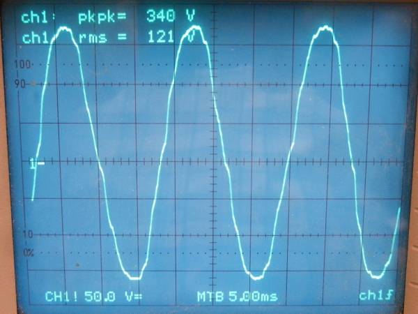
The RMS voltage is approx 120V
The peak voltage is 170V
The peak to peak voltage is 340V
So imagine you plugged a powerful 8 ohm directly into an electrical wall socket. You would hear a nice loud 60Hz hum.
So, how much power would the speaker be dissipating?
P = [(120V)^2]/8ohm = 1.8kW
also
P = [(170V)^2]/[2(8ohm)] = 1.8kW
If we used Vpp = 340V in the equation, we would get
[(340V)^2]/[2(8ohm)] = 7225W
Now check this by calculating the current
I = P/E = 7225W/120V = 60.2A
Seems too high... We know that
I = 120V/8ohm = 15A
As for the amp, like you said, how much power do I really need? For me, I think the answer is as much as I can get!
Partly because when people see the amp they will think "man that must be a super powerful amp!" and I don't want to say "No, its just 30W per channel..."
More FETs & resistors are on order.
Pass DIY Addict
Joined 2000
Paid Member
Yes, I think we weren't connecting in terminology... no worries. Something still seems strange to me about your power output. Grey's original design put out 38w into both 4 and 8 ohm loads with 15v rails and 4.5A bias. I think you should be seeing more power output with 24v rails.
Responses:
Well, let's just put it this way: just be careful not to burn yourself on it
-OR-
Yep, when's the last time you felt an amp that puts out this much heat?!?
One of my friends thought I was building a radiator or space heater when he first saw the chassis in progress. I told him it was an audio amplifier for just one speaker...
"man that must be a super powerful amp!"
Responses:
Well, let's just put it this way: just be careful not to burn yourself on it
-OR-
Yep, when's the last time you felt an amp that puts out this much heat?!?
One of my friends thought I was building a radiator or space heater when he first saw the chassis in progress. I told him it was an audio amplifier for just one speaker...
A space heater yeah, they’re definitely winter amps!
Yes Eric, I believe you are absolutely right that I should be seeing more power out of my amp.
Ideally my amplifier into 8 ohms should be putting out
Vpeak = 44V
Imax = 4.76A
Pcontinuous = 91W
So, that leads me back to the original reason I started this post lol. Why is my amp choking?
Perhaps I’ve made an error calculating my AC current gain...
Unfortunately I can't make any more measurements right now because I have things torn apart so I can add more FETs.
I am going to double the output FETs from 4 to 8, and bias them at 1.5A each, for a total of 6A.
Hopefully I find something along the way that I’ve overlooked.
Anyway, thanks Eric for bouncing ideas around with me.
Pass DIY Addict
Joined 2000
Paid Member
Hey, no problem! It's fun kicking things around. Many here have helped me, so I'm trying to give back to the community - though it seems that we've had our own private party here...
I have two primary thoughts about your output power. One, perhaps something is amiss with your AC current gain. This is a part of the circuit that I don't understand well. When I played with this before, I got exactly opposite behavior from what everyone else was posting. I am not quite sure and this part of my web page needs to be updated but I'm not really motivated to play around on my circuit board at this point (I'm too busy enjoying music and movies in my theater).
The second thought is that perhaps your output mosfets are simply current starved. For each rail voltage, there is an "optimum" minimum bias level for things to operate properly. Similarly, for each bias level, there is an "optimum" rail voltage that allows the amp to really sing. I wonder if 4.0A is just too low of a bias point for your rail voltage...
Other semi random questions:
Are you using balanced or unbalanced inputs? The amp is really designed for a balanced input and produces more output for a given input with balanced vs unbalanced. It is essentially one Aleph amp for the Pos input signal and a second Aleph amp for the Neg input signal.
Are you letting things warm up for an hour before you begin to do your measurements? What are your relative and absolute DC offset readings after the amp has warmed up? Large amounts of either will limit voltage swing on the output leading to premature clipping. Ideally, both should be below 200mV steady state.
Remember, when paralleling output mosfets, they need to be carefully matched so one doesn't hog power from the other.
- Status
- This old topic is closed. If you want to reopen this topic, contact a moderator using the "Report Post" button.
- Home
- Amplifiers
- Pass Labs
- Aleph-X Waveforms and Questions