F5 Turbo V2
Upon buying all parts , boards, cabinets, I've went almost to over 50% of this fantastic 511 pages thread and noticed some issues that other members came up to.
I was in fact wandering if a kind of items or revision that a new builder should look at before soldering his boards.
I tooked some noted and like to share ;
- Thermistors from post # 4885, insulation of thermitors to ground is very important.
- Oscillation problem, add some 3n9 or 4n7 small caps to R7 /R9.
- Soft start and DC offset protection circuits
-Bias R5/R6 resistor mod at 1,3Kohms.
Off course I might have missed some other considerations, but think that some experimented members could add some more information is quite welcome.
Unbalance of P-channel vs. N-channel
Hi all!
I have 90% completed my V2 and tested it by sound and am more than happy with that. One severe problem holds me from closing the box:
Bias so far is set to modest about 850...900mA, both channels. All 4 output boards have separate and identical heat sinks which should be OK for a bias of 1A easily. Touching the sink of the 2 P-channel boards, the temperature is lukewarm and I can touch it forever which is as expected at 800-900mA. Touching the N-channel boards they feel really hot and I have problems holding my hands there for such 5 sec's which NP is teaching us.
I have measured bias for all 4 boards separately directly at the 1Ohm resistors (rather than TP's) and they are all reading same current within few mA. Also supply voltage is identical to 0.1V both polarities and both channels. The devices are IRFP240/IRFP9240 from VISHAY. I have matched Vgs such, that Delta is around 0.1V on every board. Even the Delta beween P and N is <0.2V on each channel. DC-voltage at output is around 10mV, going up/down slightly over time.
So suspicion is, that the ON-resistance of the P- and N-devices is significantly different, heating up the N's more than the P's.
Anyone having had same symptoms?? Any suspicion about root cause? Any good advice of a therapy????
thermal interface between mosfets and heatsink must be uniform
what you're using ?
all screws tightened in same amount ?
find a way to measure temperature ; difference between mosfet case and heatsink just near by can't be higher than 10C
and yes , naive question - are positive and negative rails of same value ?
what you're using ?
all screws tightened in same amount ?
find a way to measure temperature ; difference between mosfet case and heatsink just near by can't be higher than 10C
and yes , naive question - are positive and negative rails of same value ?
That doesn't sound right. If you have the same voltage and current on the P and N side, the power and thus heat dissipation should be the same. If the transistors are not mounted properly on the cool heatsink then those transistors themselves would likely burn up because the thermal resistance to the heatsink would need to be much higher for it to be that much cooler than the second channel. I would check the source resistors and make sure they are all the correct value. If the ones on the cool heatsink are much higher in value it would cause the difference you are seeing. Also verify that you have no open connections or short circuits on the boards.
On resistance difference of the FETs would not change the power dissipation but changes in the source resistors would because you are using the voltage drop across them as a means of measuring the current.
On resistance difference of the FETs would not change the power dissipation but changes in the source resistors would because you are using the voltage drop across them as a means of measuring the current.
Unbalance of P-channel vs. N-channel
Thanks for supersonic return!
Answering questions first:
* Rail voltage is exactly + and -36.5V with load, pretty stable.
* All source resistors are 2x1Ohm ll = 0.5Ohm. This is measured yesterday evening, but only N-channel boards. I will check the P-channels later today making sure, they dont differ, causing the imbalance. The P-channels are really "cold" so this might be the reason, but why both P-channel boards??
* Heat sinks are 4 times 300x165x40mm each one for 1 board only! They are 0.31°C/W. Mounting situation slightly differs but shouldn't account for such drastic temp difference. If the devices would not be tightened properly, the FET's on the hot sink should be cool and the ones at the cool sink should be hot. That's not the case!
* DC-voltage measured at source resistors is around 420-450mV, about equal for all 4 boards and measured in 6 places. Will check the remaining 2 test points later today.
Thanks again.

Unbalance of P-channel vs. N-channel
Yes 6L6, I thought about the diodes as the other suspects as well. Touching them does not feel odd (... as ZenMod says, "feelings" are not always sufficient). Of course, the ones on the hot board are heated up by the sink. I used the MUR3020 by VISHAY. Testing them in the circuit is not easy. Using an Ohm meter gives you always a 0 Ohm reading.
Yes 6L6, I thought about the diodes as the other suspects as well. Touching them does not feel odd (... as ZenMod says, "feelings" are not always sufficient). Of course, the ones on the hot board are heated up by the sink. I used the MUR3020 by VISHAY. Testing them in the circuit is not easy. Using an Ohm meter gives you always a 0 Ohm reading.
Thermal unbalance of P-channel vs. N-channel
Measured all 8 FET's:
All source resistors measured are 0.5 Ohms.
All voltages at these source resistors measured simultanuously are identical in the 400-450mV range. I always measured one stereo channel at a time, all 4 resistors simultanuously.
Started making shots but battery of camera had gone. Will do tomorrow, but don't think it will contribute much.
I still wonder about the diodes and rather would think they are shot and do reduce R-source immediately after switch on rather than slowly getting more conductive. Is there an easy way finding out without unsoldering them, which is quite elaborate? Usually the nasty way is always the one you have to go, right?? If I cut the "common" pin of the MUR, the voltage measured across R-source in life operation should drop significantly below the 400mV, right???
Thermal unbalance of P-channel vs. N-channel
As recommended by ZenMod have measured Iq with an Amp-meter for all 4 boards (P-channel right, N-channel right, P-channel left, N-channel left). I have opened the solder joint "Ve+" and "Ve-" and placed the DMM between the boards "Ve" solder spot and the neg/pos rail coming from PSU.
The readings for all boards are identical in between 1.6A...1.7A after a 5 min warmup. This confirms the current readings measured via voltage drop over R-source. While this test suggests that everything is fine with my F5T at the same time, this way I am loosing my last suspect of a root cause for the thermal inbalance which was the MUR3020's across the 1R resistors. They seem NOT to carry a share of the source current, right??
I still need to find a contactless temp sensor.
Any further suggestions from your side Gents???
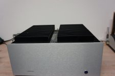
Attachments
")
- Home
- Amplifiers
- Pass Labs
- F5 Turbo Builders Thread