High power supply ripple. Hints?
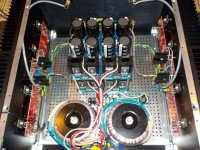
I built a F5T V2 with dual mono PSU's using 2 of the V3 boards from the store. Currently running at +/- 40 V DC rails with 2 300 VA transformers. Following Nelson's diagram, I implemented a ground isolation system with a diode bridge, thermistor and capacitor.
The amplifier sounds great with the exception that it presents a low level of noise that can be heard at the mid range and tweeter drivers.
There is no humming at the woofer.
Each dual rail power supply has 120,000 uF of filtering. 8 15,000 uF capacitors 50 V DC. Using and oscilloscope I can see a ripple of around 32 mV rms, 120 Hz with the amplifier boards connected. It drops to almost zero with no load.
What do you recommend to do to improve the amplifier?
Thanks in advance for replies.
Attachments
You say there is no hum from the bass speakers and that there is noise from the Mid and Treble speakers.
Seems noise is your problem, not hum.
The measurements you give for ripple are related to minimising hum.
Have you measured the Hum+Noise at the amplifier output?
What are the sensitivities of the three speaker drivers?
Do this with the inputs shorted with zero ohm dummy plugs.
Repeat with long interconnects, again shorted at the far end with zero ohms dummy sockets.
Repeat with long interconnects to a source with the vol pot turned right down.
Post all the results.
Last edited:
Thanks Andrew. I suspect a grounding issue. Last night I managed to blow the output FETs on one channel. Amp is back in service. While on the bench:
DC offset with open RCA input and no speakers connected: less than 50 mV. I connected a shorted RCA male to the input, the DC offset jumped to a bit more than 0.5 Volts.
If I plugged an interconnect to the input the DC offset jumped to a bit under 0.5 Volts even with the other end in the air, about the same if connected to a source. Connecting speakers did not change these values much.
I adjusted the DC offset with the input shorted, below 30 mV now, does not change much with the speakers connected. This remains true as long as there is an inout connected, when an input is removed, the DC offset goes up to around 0.5 V. What is happening?
I don't know how to measure Hum+noise, what tool(s) do I need for this?
The speakers are NHT 2.9's sensitivity is specified at 87 db.
Reports on test suggested:
With open inputs the amplifier is quiet.
With shorted dummy, noise is present but not low.
With short interconnects more noise.
With long unshielded noise is stronger with open end, stronger with cable in vertical position, less in horizontal position. (RF interference?)
With long cable if a short de end to plugged to the amplifier, noise drops to low level.
With cable connected to a source is quieter with short shielded cables than unshielded and long cables.
If source is off but connected to amp the level of noise is greater.
Next thing to try tomorrow is the install two ground rods to improve the grounding system of the electrical system of the house. Isolated grounding? May be, I will keep chasing. I think is a grounding issue... we will see.
I see two possibilities.Thanks Andrew. I suspect a grounding issue. Last night I managed to blow the output FETs on one channel. Amp is back in service. While on the bench:
DC offset with open RCA input and no speakers connected: less than 50 mV. I connected a shorted RCA male to the input, the DC offset jumped to a bit more than 0.5 Volts.
If I plugged an interconnect to the input the DC offset jumped to a bit under 0.5 Volts even with the other end in the air, about the same if connected to a source. Connecting speakers did not change these values much.
I adjusted the DC offset with the input shorted, below 30 mV now, does not change much with the speakers connected. This remains true as long as there is an inout connected, when an input is removed, the DC offset goes up to around 0.5 V. What is happening?
Either:
a.) the amp is oscillating when the open input has an aerial picking up interference attached,
or
b.) You have a DC coupled input and the source "resistance" seen by the input changes when you change the source connection.
You need an AC voltmeter. I use a variety of cheap digital voltmeters that have a 199.9mVac scale and even though they are not accurate they give a very good approximation to the H+N at the amplifier output.I don't know how to measure Hum+noise, what tool(s) do I need for this?
A 1.999Vac scale is not sensitive enough to get reasonable estimates of output H+N.
These two results are the opposite to what we usually find for a normal power amplifier. The quietest operation is usually with a zero ohms input plug fitted to each input.The speakers are NHT 2.9's sensitivity is specified at 87 db.
Reports on test suggested:
With open inputs the amplifier is quiet.
With shorted dummy, noise is present but not low.
An interconnect with an open remote end acts as an aerial picking up interference. This is generally noisier than any other connection.With short interconnects more noise.
Yes, the shield is the return route for current entering from a source. Where no source is connected the interconnect core acts as an interference pick up aerial. The screen does not provide effective shielding for an open ended core.With long unshielded noise is stronger with open end, stronger with cable in vertical position, less in horizontal position. (RF interference?)
This is normal. The short at the remote end is a test I recommend when testing a stereo amplifier. Connecting two long interconnects is the next stage. then shorting the remote ends together is the third stage. shorting the remote end screens together is a test to find your amplifiers tolerance to being connected to a stereo source that has a common "ground" for the signal returns.With long cable if a short de end to plugged to the amplifier, noise drops to low level.
This is a bit unusual. With an interconnect cable terminated at both ends, it normally makes little to no difference to the noise from the power amplifier. Maybe one of your interconnect cables is faulty?With cable connected to a source is quieter with short shielded cables than unshielded and long cables.
This is quite common. An OFF source can present any of a variety of source impedance to the input cable and the input stage. If the OFF source impedance is higher than Zero ohms, then some noise will be added to the input and may become audible, certainly measurable.If source is off but connected to amp the level of noise is greater.
NO !!!!!!!!Next thing to try tomorrow is the install two ground rods to improve the grounding system of the electrical system of the house. Isolated grounding? May be, I will keep chasing. I think is a grounding issue... we will see.
Do not alter a correctly installed mains distribution system.
If you suspect a fault in your mains system get a qualified electrician to come and check your installation.
The reason for NOT adding Earthing Rods is due to the voltages and currents in your locality during an electrical storm. With the correctly installed earthing system that the mains electricity distribution company has provided, the whole house and you and all your wiring is at the same voltage during a lightning strike nearby.
You must NOT interfere with this. Your life depends on that equality of voltage during the nearby lightning strike.
If anyone installs extra Earthing Rods then there exists the strong probablility that two different voltages can appear at the two Earth rod installations and you end up with differing voltages between the two rods during a lightning strike.
If you were unfortunate enough to be very close to a high potential difference (say an output socket relative to the floor of your house) you could get a lightning arc from the socket to you, through you to your floor. You have added an unauthorised and untested earthing rod that bring the lightning INSIDE your house !
Similarly electrical equipment connected between the two differing Earth Rod installation could end up with a high voltage between them and get damaged/destroyed.
Last edited:
Andrew, thank you for your reply. I have no gotten back to it due to work. I will dig in a bit more with different internal wire layouts and make sure that I have a good grounding system to sink noise before it reaches the amp's input. I am using long (1.5 m) Kimber unshielded interconnects, these may have to go as well if found to be the problem.
bias is hardly an issue , if you got it in proper temp equilibrium
what you need to triple check is oscillation - maybe is best to mount (increase) those lag caps in feedback network
Papa is Old Devil with zillion miles under the bu.....m , having entire circuit on one pcb , with controlled patterns thus capacitance of traces etc. , so he can do it without lag caps
put some 3n9-4n7 caps across R9 and R7 , be sure that preamp is flawless regarding transients and oscillation , simply because F5 is pretty much Lucky Luke fast
and - install decent speaker protection modules
something with μPC1237 will do ...... you can even make it as separate unit , with internal PSU
I would shoot with shotgun any amplifier responsible for burning my precious RCAs
A good idea to use those styroflex I have laying around ?
33Vdc rails
1mA through divider is enough
use 12K for R27/R28 and 18K for R25/R26 (ref. to F5Turbo V3 , page 13/17 of article)
you'll have +/-13V2 at cascode bases , and around +/-12V6 at JFet drains
Zen Mod,
sorry for digging this old post out, but do I understand it right that you aim for the lowest current through R27/R28 ? Noise ?
Thanks,
Max
A good idea to use those styroflex I have laying around ?
if they're good , why not
if Papa can use them , you can too
though , I don't like tubular stryroflex
Zen Mod,
sorry for digging this old post out, but do I understand it right that you aim for the lowest current through R27/R28 ? Noise ?
Thanks,
Max
no need for more ........ impedances are higher , thus filtering less critical (cap from bases to gnd)
Low Bias - R5/R6 resistor change suggestions
I am building the Turbo V2 with quad matching Toshiba JFETS from punkydawgs on eBay (ostensibly 6.5mA-7.9mA Idss, although I haven't been able to measure) and standard 32V PSU rails. I am using the Deluxe 5U chassis.
I am having trouble with low max bias measurements. On one channel, I was only able to measure a max 170mV of bias across the source resistors with 0 DC offset, while on the other channel I was able to max out at ~190mv with 0 DC offset. These measurements were taken with inputs shorted and with a standard power cable attached (no light bulb). The amplifier works with these settings and gets warm to the touch, but the bias is not optimal. (There is also a very slight 60hz hum that I believe I can eliminate with some layout optimization.)
I understand that I can boost the max bias by increasing the values of R5/R6 from the standard 1Kohm. Does anybody have any suggestion for a starting point for the R5/R6 resistor change? My target bias is 3.5mv, so essentially double what I am able to measure right now. I suppose I would be willing to settle for anything over 3mV.
Another thing I noticed that may be significant is that I did not observe the "2 steps forward, 1 step back" phenomena described in the build guide when I adjusted bias. One knob would increase bias and take DC offset below zero, as described in the build guide. When I took zeroed DC offset with the other knob, however, bias would continue to increase.
I'm guessing you meant 350mv rather than 3.5mv across source resistors. Many have had the same issue (myself included) and changing R5/R6 = 2 to 2.2k should resolve it.
On a related note, when I upgraded my V2 stereo to V3 monoblocks I doubled up the jfets (2 pair per channel) I left R5/R6 at 2.2k. The pots were much more sensitive to adjust and bias started to increase much sooner (less turns of P1/P2), BUT, I also noticed the bias was much more stable. It also changed a LOT less from cold to warmed up. Not sure if it was due to the doubled jfets, resistor change, or both but I'm happy.
On a related note, when I upgraded my V2 stereo to V3 monoblocks I doubled up the jfets (2 pair per channel) I left R5/R6 at 2.2k. The pots were much more sensitive to adjust and bias started to increase much sooner (less turns of P1/P2), BUT, I also noticed the bias was much more stable. It also changed a LOT less from cold to warmed up. Not sure if it was due to the doubled jfets, resistor change, or both but I'm happy.
Thanks - yes, I did mean 350mV I have some spare 1.2K resistors, so I'll plan on inserting those in series with the existing 1K resistors on the board for a total of 2.2k resistance, reset the pots to zero, and re-bias from there.
My bias measurements were pretty stable as is, but I'm guessing that is because the heat sinks never really heated up beyond warm.
I did manage to spark a hole through the substrate on one of the the p-channel output boards during my last biasing session when an alligator clip attached to one of the source resistor test points made contact with the substrate and created a short with the embedded copper ground trace. It gave me a good scare, but thankfully, the mosfets weren't damaged and I was able to insulate the exposed trace with a piece of electrical tape.
I have some spare 1.2K resistors, so I'll plan on inserting those in series with the existing 1K resistors on the board for a total of 2.2k resistance, reset the pots to zero, and re-bias from there.My bias measurements were pretty stable as is, but I'm guessing that is because the heat sinks never really heated up beyond warm.
I did manage to spark a hole through the substrate on one of the the p-channel output boards during my last biasing session when an alligator clip attached to one of the source resistor test points made contact with the substrate and created a short with the embedded copper ground trace. It gave me a good scare, but thankfully, the mosfets weren't damaged and I was able to insulate the exposed trace with a piece of electrical tape.
As takitaj recommends worked for me also..The two forwards one back bias setting up will become apparent once you can drive the bias up..The thing that I noticed is the 'time' it takes to reach thermal/bias equilibrium. Having built a few now (V3's ) is that you must give it time to come up to temperature.
I power up and dial in 100-150mv of bias, 0 the offset, put the lid on and leave alone for a few hours, obviously checking readings now and again. For me a min of 4 hours is the time frame I use to set bias/offset. This initial bias setting of 100-150mv may rise to +200mv during this time.
With my first build I set the bias at 250mv over the first hour or so, lid on and walked away for another hour. On my return it was +500mv and rising.....
The tricky bit is, to adjust the bias you have to remove the lid.....in doing so the internal temperature drops along with the bias...You get a 'feel' for it after a while and under bias with the lid off. It took me three days to set my amps to where I'm happy to leave them on all the time if I feel so inclined. Not that I do.
Kyle, good luck with your project. It looks like it's going well. Please report on the quality of the jfets you bought from punkydawgs and the hum issue.
I'm on the sideline about building the V3. I have a V2 running on +/- 40 Volts rails, dual mono PS with quad jfets in the front end board. I did not have issues biasing the output devices using Nelson's original schematics.
You will love the amplifier sound... Best amp I've hear in my life.
I'm on the sideline about building the V3. I have a V2 running on +/- 40 Volts rails, dual mono PS with quad jfets in the front end board. I did not have issues biasing the output devices using Nelson's original schematics.
You will love the amplifier sound... Best amp I've hear in my life.
Channel Board varnishing
Hi KyleMD,
the red lacquer layer over the P/N-channel boards indeed gave me a similar accident as you had one:
I was using standard metal washers beneath the screws bolting down the board. The washers were just wide enough to extend over one of the hidden copper lines below the varnishing. Obviously, I tightened the bolts a bit too much and so the lacquer cracked and the washer made contact to the copper line which caused a short. I am now using in addition to the metal washer a plastic washer for insulation.
Thanks laverda for the detailed description of your biasing procedure. I have not done it as systematic as you do but in essence I do the same thing. I am starting at a medium bias level and correct biasing and offset up/down as they have drifted after hours of operation. Once bias/offset settings are getting stable I start increasing the bias and the procedure starts again until you arrive at your final target of bias.
Bad news. I installed the new resistors, but somehow the amp no longer passes the lightbulb test. I've isolated the issue to the power supply. I've disconnected all the amp boards from the supply. With the light bulb on the power cord I measure ~4.5 volts A/C going into the transformer mains, but the LEDs do not light up on the PSU board and I don't measure any DC voltage on the output terminals. I'm certain almost it's not an issue with the wiring or cap polarity because the PSU was working faultlessly just a few days ago. I'm wondering if the diodes on the rectifier boards somehow failed.
I pulled apart the power supply this morning.
I'm getting voltage on both primary windings from the transformer when I disconnect them from the rectifier board.
When I connect the primaries to the rectifier board, I don't measure any AC voltage across the A/C terminals before the rectifiers. I also don't measure any DC voltage out of the rectifier boards. The rectifier boards pass a diode test with the multimeter, so I'm guessing there's a short between the rectifier board and the chassis, but I can't find it for the life of me.
It's definitely a short between the rectifier board and the chassis, as I'm measuring an AC voltage between one of the AC primary inputs and a mounting screw into the chassis stand-off. Unfortunately, I'm still not able to locate the short. All of the solder connections look good and there aren't any loose wires. I even vacuumed out the chassis in case there were any loose strands, and I changed the stand-off height to move the board further from the chassis, but I'm still getting the short. I really have no idea how this developed, as the power supply was working perfectly a few days ago.
Next step is to get some rubber washers to insulate the board from the standoffs. If that doesn't work, I'm all out of ideas.
Next step is to get some rubber washers to insulate the board from the standoffs. If that doesn't work, I'm all out of ideas.
- Home
- Amplifiers
- Pass Labs
- F5 Turbo Builders Thread