Here ya to V3. No diodes, but overal bias higher than my V2. No miller compensation cap for instability. No heavy testing, but small stuff checks out fine.
Buzz,
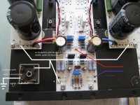
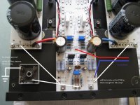
In this setup on your photo you did use the 'jumper' on the PSU boards, to connect the two grounds.
But in my setup with the two PSU boards separated, should I connect this 'jumper'? Or put a ground wire of each PSU board to the F5T convertible AMP board?
Because on the AMP boards there is a coppertrack on both sides connecting the two PSU-G 's. So i think I will introduce a ground loop if I connect the 'jumper' on the PSU boards also...
Are you still with me? Sorry if it is not clear...
That point becomes star ground. It is from that point that you ground the entire circuit to earth through the CL60/Bridge combo(Ground lift). What is important is that you have a central point to return all the power grounds to. The main board becomes your star ground for the signal wires. In truth, you could take signal grounds to PSU as well, but it is convenient and noise free just to take them to the boards, plus it allows for twisted pairs to the inputs and outputs.

I don't understand what is not ideal? Should the grounds of both PSU's be closer together? What if I connect both grounds with very thick wire or copperstrips?
How do I get it ideal?
When to connect both grounds together? (Same transformer)
IMO if you have derived both channel PS from same secondaries of one transformer then you are going to get one ground loop when both inputs grounds are connected. Then you need to connect both grounds together at the output of PS. This case applies mostly for floating ground not necessarily transformer CT as ground. But ground from same transformer CT may also need this.
If its required to connect both grounds together then I suggest using thickest copper wire (at least 4X of transformer lead thickness).
When its not required?
While both channel PS are distinct, I mean two transformers or different secondaries, then its not required. Here both grounds are separate. It does not matter if they are connected together. While connecting both of these (floating?) grounds one must use ground isolaters to keep them distinct.
2SK1530 and 2SJ201 for F5 and F5 Turbo
I would like to alert F5 Turbo builders that I have just put up for sale in this thread a significant number of the very good Toshiba 2SK1530 and 2SJ201 MOSFETs perfectly suited for the F5 and F5 Turbo variants.
Here is what Mr. Pass has to say about these Mosfets in the F5 Turbo manual:
"A number of DIYers have speculated on or even tried the Toshiba 2SK1530 and 2SJ201 Mosfets. These are really nice (discontinued) audio transistors and are very fine for F5's, but keep in mind that with a 12 amp rating they have a smaller maximum current than the Fairchield parts. This will not prevent them from sounding very good, however, and I do recommend them in general."
The quality of device matching is extraordinary (@ operating conditions) and I have set the price so that everybody should be able to enjoy these fantastic Mosfets without breaking the bank.
Enjoy")
I would like to alert F5 Turbo builders that I have just put up for sale in this thread a significant number of the very good Toshiba 2SK1530 and 2SJ201 MOSFETs perfectly suited for the F5 and F5 Turbo variants.
Here is what Mr. Pass has to say about these Mosfets in the F5 Turbo manual:
"A number of DIYers have speculated on or even tried the Toshiba 2SK1530 and 2SJ201 Mosfets. These are really nice (discontinued) audio transistors and are very fine for F5's, but keep in mind that with a 12 amp rating they have a smaller maximum current than the Fairchield parts. This will not prevent them from sounding very good, however, and I do recommend them in general."
The quality of device matching is extraordinary (@ operating conditions) and I have set the price so that everybody should be able to enjoy these fantastic Mosfets without breaking the bank.
Enjoy
Has anyone built a F5T with the toshibas? I was wondering if the source resistance or bias needs to be changed.
Has anyone built a F5T with the toshibas? I was wondering if the source resistance or bias needs to be changed.
Nelson say: "or even tried the Toshiba 2SK1530 and 2SJ201 Mosfets", but I guess this refers to the F5/F5X and not the F5 Turbo.
Nevertheless, I see his comment as a warm invitation to try
I don't need the power of the F5 Turbo, but I do hope that the (very) low cost of the Toshiba FETs I'm offering will inspire somebody to try and report back.
I guess one would lean towards more output devices and lower bias in the case of the Toshiba's to keep current/fet lower, but that is just my unqualified guess
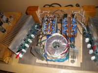
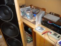
OK so I didn't build it , but thanks to the extreme generosity of a fellow member I have been listening to this for a few hours. Fairchild outputs. I simply put the boards in place of my f5 boards, set the bias and sat back to listen. WOW... At first I had the bias set very conservatively, but at .5 amp per device this thing really sings. As the name implies it sounds like my f5 only on steroids. I will be adding the diodes to this build tomorrow and will report any difference. As it stands, after running a few hours, the output fets seem to have settled at 56c and the sinks are 48c. I attached some pics...don't laugh..
Evan
55 47
Evan
55 47
Attachments
- Home
- Amplifiers
- Pass Labs
- F5 Turbo Builders Thread