I would say it to some degree depends on the distance from OPT
the bliss of very large supply caps is mostly a myth created by Jean Hiraga
might be worth to note, at the time when he did his study with the 8watt Monster, using very large 'computer grade caps', those were probably better quality ..... but today, cards may have changed hands
the bliss of very large supply caps is mostly a myth created by Jean Hiraga
might be worth to note, at the time when he did his study with the 8watt Monster, using very large 'computer grade caps', those were probably better quality ..... but today, cards may have changed hands
60,000uF per channel is quite a bit lower than the recommended 160,000 for stereo. Two of those per channel should be perfect, though.
Thanks, might just be better to build one myself! well i guess its all trial and error and finding what works best.
Another question, i found this nice pre-amp kit it seems a clone but i really like the idea of it, you think this would marry up with F5 ok ?
NAIM NAC42.5 KIT Pre-amp > B1 > F5
I know its a clone but surely it can't be that bad can it ? lol
Last edited:
Yes, just that im building this amplifier for a friend so once its done, i could have to travel 600mile to see him to add pre-amp. if he felt he needed it.
What source will he be using? Look up output voltage. Also what speakers, efficiency?
Let us know here and we can help with that.
Rush
Could I build a mild v2 turbo by using two pairs of mosfets and diodes over the resistors, but using only the original f5 18v psu transformer? I´m building an f5 now, and I´m already considering how to improve it. 
If I´m thinking correctly this would not give me an improvement in watts, but could make it a lot more powerful at difficuld loads?
Thanks for any thoughts on this!
If I´m thinking correctly this would not give me an improvement in watts, but could make it a lot more powerful at difficuld loads?
Thanks for any thoughts on this!
What source will he be using? Look up output voltage. Also what speakers, efficiency?
Let us know here and we can help with that.
Rush
Thankyou very much
Speakers = 87db
Just waiting for source info
Could I build a mild v2 turbo by using two pairs of mosfets and diodes over the resistors, but using only the original f5 18v psu transformer? I´m building an f5 now, and I´m already considering how to improve it.
If I´m thinking correctly this would not give me an improvement in watts, but could make it a lot more powerful at difficuld loads?
Thanks for any thoughts on this!
As I understand the Turbo part is carried out by the diodes, thet kik in at hi voltagge so why do bother for 18 V trafos?
I am running twins on 26 V rails on 4 Homs speakers (nasty ones) and it is prety good.
IMO First decide what power you realy need
then build stock version to get taste of it
then based on that you are prety free to get up and up but ditch the 18 V traffo
About the considering to improve the F5 see abowe< build stock first>
PS the J fets can take up to 35 V rails before cascoding but cascoding only add further bonuses and the current limiters are not realy needed but get same speaker protection duda
F5, V1 PSU problem, getting 70V !
Hello
Turned on psu and amp circuits yesterday to start final set up and the little J74 / Q2 smoked, only on the left channel.
And for some reason the output from the PSU had doubled from 35 previously to 70v. I know that the little transistors have a breakdown point of 60v
Today I disconnected all 6 leads from the PSU to the amp boards. My simple test shows that I am getting +35 and -35 from the bridge rectifiers. Next test; positive lead from meter on + of PSU, and negative on PSU gives +70vdc, however placing black lead from meter on PSU GND result is 35vdc. What I have done wrong??
I f I read correctly you're p/s sounds ok.With the leads across plus to neg will give 70vdc.Connect the black lead to the centre connection between the caps and move the red lead from pos +35v to neg will give -35 hence your 70v across +-. As to the smoking jfet some one with more knowledge will no doubt chip in.Good look.
the diodes kick in when the output current demand rises too high, as determined by the voltage drop across the source resistor.As I understand the Turbo part is carried out by the diodes, thet kik in at hi voltagge so why do bother for 18 V trafos?
...................
The diodes make more current available to the load by bypassing the Source Resistor.
The diodes help to reduce the voltage lost across the Source Resistor when high currents are demanded.
It does not matter whether a the PSU is +-20Vdc or +-50Vdc, the diodes turn on at high current demand.
Last edited:
hello
this my first post on diyAudio,
i hope my english level is good for tey to build an F5T.
i have already build uP and ugs .
i see this kit :
F5T Turbo Power Amplifier kit for sales ( i have a lot of irf irfp IRF9240/240) but spencer shop is closed .
have you another source for pcb ?
thank's
fgaston
this my first post on diyAudio,
i hope my english level is good for tey to build an F5T.
i have already build uP and ugs .
i see this kit :
F5T Turbo Power Amplifier kit for sales ( i have a lot of irf irfp IRF9240/240) but spencer shop is closed .
have you another source for pcb ?
thank's
fgaston
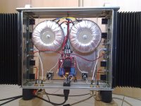
I completed my dual mono vertical box. Running successfully at source resistor voltage drop 300mV(0.6A bias) per device. Thanks again NP, all FM here and buzzforb for semiconductors.
Power Supply, mains section. I used softstart and thermal cutoff from bay.
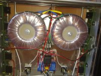
Closeup each toroidal transformer is 300VA, 2X24V secondary.
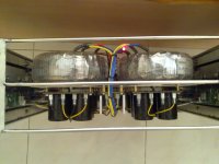
Partition separation - 7mm gap between open end of transformer mounting bolt and side panel. 5-6mm gap for power caps and side panel.
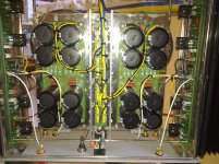
Other side of the partition, all power bank of DC voltages. I used 8 X 15000µF per channel.
Closeup of power switch and reset switch for slow start. My amp does not power on automatically on mains supply reconnection. It needs push button trigger to switch on.
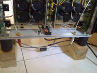
Both 75°C thermostat attached to heatsink using spring taken out from cloth drying clip.
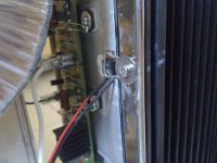
Closeup of mains earth ground isolator. Bridge connects mains ground to chassis at central mounting bolt and PS AGND comes from behind PCB at bottom.
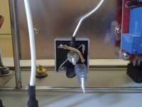
Aluminum handles fitted with M4 SS bolts. Indicator 3mm red LED into hole with 2mm opening in top and 3mm from behind on face plate. LED hole filled with transparent hard glue.
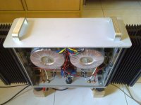
Side view of complete box.
Power Supply, mains section. I used softstart and thermal cutoff from bay.

Closeup each toroidal transformer is 300VA, 2X24V secondary.

Partition separation - 7mm gap between open end of transformer mounting bolt and side panel. 5-6mm gap for power caps and side panel.

Other side of the partition, all power bank of DC voltages. I used 8 X 15000µF per channel.

Closeup of power switch and reset switch for slow start. My amp does not power on automatically on mains supply reconnection. It needs push button trigger to switch on.

Both 75°C thermostat attached to heatsink using spring taken out from cloth drying clip.

Closeup of mains earth ground isolator. Bridge connects mains ground to chassis at central mounting bolt and PS AGND comes from behind PCB at bottom.

Aluminum handles fitted with M4 SS bolts. Indicator 3mm red LED into hole with 2mm opening in top and 3mm from behind on face plate. LED hole filled with transparent hard glue.

Side view of complete box.

that's Fugly!
mount lower and bottom plates (regularly looking as front and back ) via some spacers - to ensure some vertical air flow inside the case
Thanks ZM! Yes there is some gap (~3mm) between top and bottom plate along with side panels.
- Home
- Amplifiers
- Pass Labs
- F5 Turbo Builders Thread