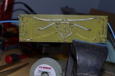
Not the problem at hand, but check this out - (Aleph 3)I have always wanted to do point to point but have always been scared and don't know how to even start such a project.
Quite possibly the coolest thing ever.

More can be seen from this page - Milan's DIY audio pages - Aleph3 amplifier
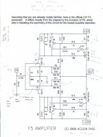
F5 Jfet connections
Hi all
Thanks for your replies
Diagram shows Q3, Gate and Source joined to thermistor, TH1
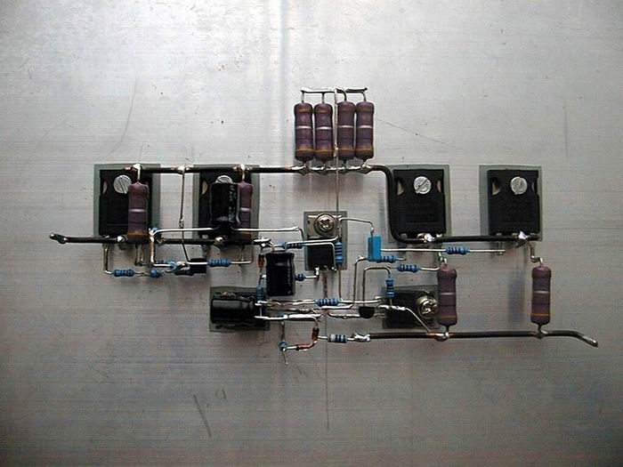
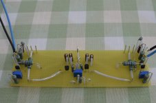
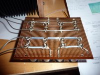
Now seeing the Aleph 3 picture (most impressed with soldering skills!) confirms I have wired it up correctly. picture shows my limited soldering skills.
Wire is 1.25mm silver plated copper.
Plan is now to solder the 3 pins/wires standing up to the jfets which are boldted already to the Conrad heatsinks
Hi all
Thanks for your replies
Diagram shows Q3, Gate and Source joined to thermistor, TH1
Now seeing the Aleph 3 picture (most impressed with soldering skills!) confirms I have wired it up correctly. picture shows my limited soldering skills.
Wire is 1.25mm silver plated copper.
Plan is now to solder the 3 pins/wires standing up to the jfets which are boldted already to the Conrad heatsinks
Attachments
Hi Steve, if you are doing this point to point the *only* connection to the gate of the FET (Q3 OR Q4) is the gate resistor (R13 OR R14).
The source of the FET connects to the source resistor (R7/R8) which also serves as the sensing for thermal (TH1/2) and the main current limiters (R15/16).
Short-circuiting the gate and source will lead to output transistor forever staying in cut-off, and looking at your board indicates you have done just that. Also, one of the output devices has the gate and source flipped over. Not sure which one, but the pins on both the N-type and P-type are identical pinout!
Last edited:
F5 Jfet connections
Hi Sangram
Thank you for answering my question, I understand what I need to change on my circuit. Having now looked again at the Jfet data sheet I have realised I have misunderstood the symbol for a JFET.
FQA12P20 pdf, FQA12P20 description, FQA12P20 datasheets, FQA12P20 view ::: ALLDATASHEET :::
Hi Sangram
Thank you for answering my question, I understand what I need to change on my circuit. Having now looked again at the Jfet data sheet I have realised I have misunderstood the symbol for a JFET.
FQA12P20 pdf, FQA12P20 description, FQA12P20 datasheets, FQA12P20 view ::: ALLDATASHEET :::
Steve,
Nice job on building this amp, you will deeply enjoy it. Correct JFET connections and she will sing! I appreciate that you shared these pics, it is a very nice approach and a nice challenge. Not like painting by the numbers such as stuffing a PCB, but truly building it yourself.
Nice job on building this amp, you will deeply enjoy it. Correct JFET connections and she will sing! I appreciate that you shared these pics, it is a very nice approach and a nice challenge. Not like painting by the numbers such as stuffing a PCB, but truly building it yourself.
Hi All
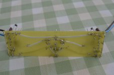
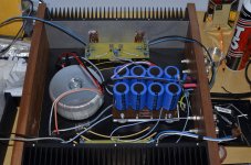
Have made the correction now to Jfet wiring. Pictures attached. Also inc a picture of the underside of the PSU. Have used 2.0mm silver-plated copper wire. The blue and black flex wires hanging of of the audio boards are for test purposes only.
Have made the correction now to Jfet wiring. Pictures attached. Also inc a picture of the underside of the PSU. Have used 2.0mm silver-plated copper wire. The blue and black flex wires hanging of of the audio boards are for test purposes only.
Attachments
Lovely Amp there!
just wondering, would this transformer do for F5T ?
Toroid transformer 600VA, 230V/2x24V/2x12,5A, dia.153x68mm, wire 150mm, 5,0kg
Toroidal transformer TST 600/224 | GES-ELECTRONICS
I ask as it looks rather small, also it says how many amps the 2x12v is but not the 2x24
just wondering, would this transformer do for F5T ?
Toroid transformer 600VA, 230V/2x24V/2x12,5A, dia.153x68mm, wire 150mm, 5,0kg
Toroidal transformer TST 600/224 | GES-ELECTRONICS
I ask as it looks rather small, also it says how many amps the 2x12v is but not the 2x24
I think id probably go with this one tho
600W Toroid transformer Input:0-115-230V Output:24V-0-24V 12V-0-12V | eBay
Hows that look for F5T ? and i think on the 12v winding i could probably somehow power the B1 Buffer. 2 birds with one stone! poor birds
600W Toroid transformer Input:0-115-230V Output:24V-0-24V 12V-0-12V | eBay
Hows that look for F5T ? and i think on the 12v winding i could probably somehow power the B1 Buffer. 2 birds with one stone! poor birds
If you adopt the dual purpose soft start and slow charge by inserting a resistance in the primary then you must use a long time delay.
If you adopt that long time delay then the consequence is resistor overheating.
But the basic problem is that a primary resistance is not effective in limiting the secondary current.
If one adopts a combination of high resistance Power NTCs to avoid the resistor overheat risk, then you will find that the secondary current limiting is even less effective, due to the large reduction in resistance of the now hotter NTCs.
It seems that my message is not getting through.
Would you all start thinking and if necessary measure the effectiveness of your slow charge proposals and report here to prove me wrong. I am sure there are many who would love that outcome and an apology from me for misleading the whole community.
There's the challenge. Prove that added resistance in the Primary is effective in limiting the charging current of the capacitors in the secondary circuit.
I have a lot of amps over here and have used soft starts consisting of NTCs inline with the primary then switched out after a delay. A couple CL-60's, 70's or 80's (10-46 ohms each).
When the relay switches out the NTCs to connect the primary directly to the AC line you can hear the inrush "booooing" into your amp. Increasing the primary resistance and increasing the delay don't do very much. Its hard to measure with a DMM because the DMM cannot lock on so good so a little tricky to see what is going on.
I can confirm what Andrew is saying, the technique of putting resistance before the primary does not work so great. Maybe it would if you really had a large amount of resistance but I have never tried anything much over 100 ohms.
That said, I've not blown any fuses with my amps so while its not perfect it seems to be doing ok.
I think id probably go with this one tho
600W Toroid transformer Input:0-115-230V Output:24V-0-24V 12V-0-12V | eBay
Hows that look for F5T ? and i think on the 12v winding i could probably somehow power the B1 Buffer. 2 birds with one stone! poor birds
Transfer Multisort Elektronik ? Online-katalog | Mer än 100 000 produkter som erbjuds
bought 4 pcs from tme. quick and easy.
I have used 140r in a couple of soft starts with smaller toroids................ but I have never tried anything much over 100 ohms.
That said, I've not blown any fuses with my amps so while its not perfect it seems to be doing ok.
Zen Mod, F5 testing process
Hello
About to turn on the amp for the first time. I have already tested the PSU which gives me 35v.
Can anyone please explain to me in layman terms what 'IQ' means in this context? Is this the low voltage across R7 and R8?
I understand the principles of 'offset' between PSU and speaker out.
Hello
About to turn on the amp for the first time. I have already tested the PSU which gives me 35v.
Can anyone please explain to me in layman terms what 'IQ' means in this context? Is this the low voltage across R7 and R8?
I understand the principles of 'offset' between PSU and speaker out.
power supply
Need a little input here, do you think id be crazy if i had one of these per channel for the power supply?
6*10000UF/50V The protection of high quality Power supply board with speaker AC | eBay
Need a little input here, do you think id be crazy if i had one of these per channel for the power supply?
6*10000UF/50V The protection of high quality Power supply board with speaker AC | eBay
- Home
- Amplifiers
- Pass Labs
- F5 Turbo Builders Thread