Dear All,
I built the F5T V2 with 500VA Transformer for both channel. Bias at 350mV/1R resistor. all are working fine and temperature on heat sink about 50C. but for listening i feel missing detail at HF and the bandwidth is narrow. removed diode(because see it could be China made) but the sound and bandwidth also the same, dynamic range not good.
Checking voltage on each 1R resistor. and see it about ~20mV difference on each power FET. is that normal?
Could any reason that make F5T V2 not good in HF and dynamic range?
Thanks.
What MOSFETs you are using - IRF or Fairchild?Dear All,
I built the F5T V2 with 500VA Transformer for both channel. Bias at 350mV/1R resistor. all are working fine and temperature on heat sink about 50C. but for listening i feel missing detail at HF and the bandwidth is narrow. removed diode(because see it could be China made) but the sound and bandwidth also the same, dynamic range not good.
Checking voltage on each 1R resistor. and see it about ~20mV difference on each power FET. is that normal?
Could any reason that make F5T V2 not good in HF and dynamic range?
Thanks.
What MOSFETs you are using - IRF or Fairchild?
I used match quad Fairchild from Buzzford
@6L6: I bought Jfet from Japan with pre-matched. don't know it's genuine or not but it good. before I can not bias with fake Jfet for F5T. but with this JFet the bias setting easily and stable. i tried both BL and V type, result the same.
I used match quad Fairchild from Buzzford
@6L6: I bought Jfet from Japan with pre-matched. don't know it's genuine or not but it good. before I can not bias with fake Jfet for F5T. but with this JFet the bias setting easily and stable. i tried both BL and V type, result the same.
what railvolt? pics?
20mV over 350mV is better than 6% matching. I would not be unhappy with that given that 4 1% resistors give a worst case matching of 4%.
The compression of sound that you hear is unusual. It is also not because of the diodes, those don't seem to be actually coming into play for most people.
IMHO 500VA seems to be on the adequate side for a single channel though, if it is for both you are slightly underpowered.
The compression of sound that you hear is unusual. It is also not because of the diodes, those don't seem to be actually coming into play for most people.
IMHO 500VA seems to be on the adequate side for a single channel though, if it is for both you are slightly underpowered.
Thanks for your reply
@oiphy: I'm running with 32VDC rail. and after 2 channel running is 30.3VDC. I will take some picture later.
@sangram: I also though because underpowered, because all the component i used is good enough, i think. can you tell me what's "sound" problem if the transformer underpowered? may it cause lost detail at Hi Frequency? I'm hearing F5T without any pre-amplifier.
No, it should read:........................given that 4 1% resistors give a worst case matching of 4%.
...................
given that 4 +-1% resistors give a worst case matching of 2%.
But, did he use 1% or 5% or 10% resistors? Did he match the resistors? Did he even measure the resistors?
It i spossible that swapping there positioning will change the amount of variation you see. The P channel seem to be more sensitive to heat variation than th eN channel. I would guess that the P channel device ais where you are seeing you differences. Whil ei woul dlik eto have everyones fets show no difference in bias, there i snow way to match them for such baried conditions. Others may have input otherwise, but i doubt you are hearing a difference of 20mV in the output. Lacking HF is a bandwidth issue an dis more a result of current, capacitance and gain. I hav elsitened to mine for 3-4 months and cannot agree with your findings on the sound. I listen to classical music and have yet to find any dynami ccompression. The offset on my P channel fets is about 12mV. N channel are within 3mV.
Ittien,
At work now, so hopefully typing will be better. What I would suggest is to remove them and rearrange them to where the Vdrop are more closely aligned.
If you have 350, 370 on one side and 355 and 375 on the other, locate the similar ones on the same side. Report back.
At work now, so hopefully typing will be better. What I would suggest is to remove them and rearrange them to where the Vdrop are more closely aligned.
If you have 350, 370 on one side and 355 and 375 on the other, locate the similar ones on the same side. Report back.
Thanks all for your input, it's really good for me to solve my issue, i think.
Attached is my current board.
All resistor is KOA 5%, but i'm NOT do measure before plugin, that would be a mistake.
I'm not install P3.
I'll do and report back all of your input. capacitor for power supply i used is Nichicon Gold Tune 10000uF/35V. as i think it good enough(?), and used 4 STTH6002 diode to make bridge for power supply. all thing i tried to do the best.
but as sangram said. power supply 500VA for both channel maybe an issue.
i will update more infor above lost HF and narrow bandwidth.
Hi There!
Maybe a stupid question? But cdoes it matter, if I use 1 watt resistors instead of 1/4 watt resistors for the F5? Thanks for the answer, Teake
Not a stupid question at all! This is DIY -- we are all learning and nobody knows it all.
")
You may always use more dissipation rating and/or voltage rating.
The 1W resistors will be very de-rated in the spots for the smaller resistors, and will be fine.
As AndrewT says, there may be a fit problem, but you can mount them 'soldier-style' if there is an issue. See photo -
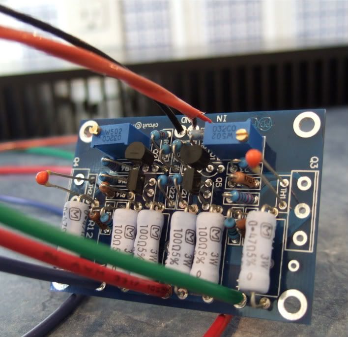
You can see that most of the small resistors are mounted that way, this PCB is made for very, very small resistors. Again, this way of mounting works very well.
Thanks all for your input, it's really good for me to solve my issue, i think.
Attached is my current board.
All resistor is KOA 5%, but i'm NOT do measure before plugin, that would be a mistake.
I'm not install P3.
I'll do and report back all of your input. capacitor for power supply i used is Nichicon Gold Tune 10000uF/35V. as i think it good enough(?), and used 4 STTH6002 diode to make bridge for power supply. all thing i tried to do the best.
but as sangram said. power supply 500VA for both channel maybe an issue.
i will update more infor above lost HF and narrow bandwidth.
View attachment 325646
Before you fire up any amp, check for proper isolation of the Fets by connecting one probe of the DMM to the drain pin of the fet and the other probe to the heatsink surface. Set it to measure resistance and you should get an open loop reading if all is OK.
No, it should read:
given that 4 +-1% resistors give a worst case matching of 2%.
Or, probably 1% when resistors are in parallel and 4% when they are in series. If it was only one resistor it would be 2%.
The only insight I can offer to ittien on his problem is that I tend to agree that even severely mismatched current sharing will be less of a probable issue than fake input devices (setting bias properly is not an indicator), a failed input stage, or a problem in the power supply. I ran a F5 off a 150VA transformer for each channel and while it worked, the results weren't as pretty as I hoped. Switching those out for 400VA units, one per channel, really boosted the performance.
- Home
- Amplifiers
- Pass Labs
- F5 Turbo Builders Thread