Would you believe Nelson Pass?
http://www.firstwatt.com/pdf/art_power_supplies.pdf
http://www.firstwatt.com/pdf/art_power_supplies.pdf
Originally Posted by buzzforb View Post
A toroid that is 3 to 5 times the dissipation amount is the best way to calculate things............
I would say it depends on output power
smaller amps might need more 'headroom' because you probably push it harder
small amps, a factor 10 is not hard to achieve
with very big amps, a factor 5 might make more sense
This is main reason I have suggested further off site investigation. In reality, multiple factors are involved. Do you base it on rated power or dissipated power? Dissipated power is easy, rated, not so much. My generalizations are just that. OTOH, I have built an F5TV2 with an undersized 400VA toroid and it plays music. Check the GB thread for specific numbers from Antek, if interested.

All this configuring XFRM's and power disapated/output does seem to confuse to many. There are plenty here who know these things. There are also slight differences in the terminology and casual statements that are not clearly defined. There is also the feeling that after helping someone, a week later there is another one? and another? and there isn't really any digging it out or reading through the thread, just explaining and answers. Some of you feel insulted, useless and even pissed. But, the people who keep answering over and over (the ones that know what their doing) are not happy dealing with it this way either.
These are basic electonics issues. The very first coarse you take on the road to elec eng will probably drive home some AC/DC theroy and Ohm's law. Nelson's papers and coments are good but, you need a "little" understanding if you are going to go with the "rules of thumb". More understanding if you are actually evaluating the big picture using all the numbers.
I have seen some confussion here regarding output watts: peak, avg or rms?
Also, Output Rail voltage being stated as actually only the output voltage and no accounting for FET loss?
I think the biggest issue though might actually be the rediculous desire for MORE WATTS. What is that? If we were all talking ClassA, Class AB etc. there could be a good discussion but, I don't see everyone on the same page ussually? To me, if you want 150+ Wrms of classA power there is something wrong with this picture. The power disapation of 1 amp like that will heat a room in winter all by itself. You might need the air conditioner to use stereo amps in the winter. And the cost and size/weight. Maybe new speakers would be cheaper? The F5 and variants are a very good, simple, High bias ClassAB amp with the capability for substantial average ClassA listening level while also providing a comfortable amount of headroom for transients and peaks.
Along these same lines, there is a very good test to understand a little what is necessary in your system at this thread http://www.diyaudio.com/forums/mult...much-voltage-power-do-your-speakers-need.html
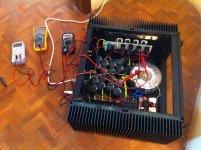
Completed F5 Turbo V3
Finally, after months of putting together various pieces, I completed the F5 Turbo V3 today gifting myself for the new year!
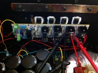
Basically the V3 is built around Teabag's boards using 4 pairs for each channel. The schematic is exactly the way it is on NP's article.
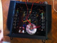
The AC rail voltage is 32V and gives 47VDC per rail after rectifier and caps on no load condition. The toroid is 1KVA, 2 X 32V. The capacitors used are Panasonic CE THA model 27000 uF, 63V X 8 per rail in a CRC config.
I have used a soft start switch from ebay, which seems to work well with a push button start switch.
The amp is turned on - no problems. Check with bulb first, no problems. Biases well and offset is stable after adjustment. No hum, no noise cannot even make out that the amp is on when a test speaker is connected, with inputs shorted as well as open.
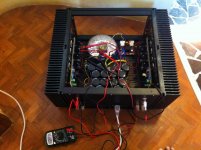
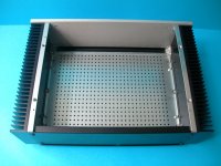
The chassis is massive with huge heatsinks. A similar chassis handled V2 with ease. But I can tell you that the V3 is a different ball game. The heatsinks get quite hot. The 4 pairs push heat like hell.
Only concern right now is that I have biased each output transistor at 300mV when quite hot. At that bias setting, when started cold, it starts at 75mV and climbs all the way to 300mV in a matter of 1 hour. Is this normal. Is the thermistor control working? I have made sure that the thermistors are touching the heatsink and have also applied heatsink goop for better conduction.
I want to see the bias stop at 300mV and climb no further. I have right now kept it under observation.
Any comments and advice appreciated. Attached are some of the pictures.
Thanks.
Finally, after months of putting together various pieces, I completed the F5 Turbo V3 today gifting myself for the new year!
Basically the V3 is built around Teabag's boards using 4 pairs for each channel. The schematic is exactly the way it is on NP's article.
The AC rail voltage is 32V and gives 47VDC per rail after rectifier and caps on no load condition. The toroid is 1KVA, 2 X 32V. The capacitors used are Panasonic CE THA model 27000 uF, 63V X 8 per rail in a CRC config.
I have used a soft start switch from ebay, which seems to work well with a push button start switch.
The amp is turned on - no problems. Check with bulb first, no problems. Biases well and offset is stable after adjustment. No hum, no noise cannot even make out that the amp is on when a test speaker is connected, with inputs shorted as well as open.
The chassis is massive with huge heatsinks. A similar chassis handled V2 with ease. But I can tell you that the V3 is a different ball game. The heatsinks get quite hot. The 4 pairs push heat like hell.
Only concern right now is that I have biased each output transistor at 300mV when quite hot. At that bias setting, when started cold, it starts at 75mV and climbs all the way to 300mV in a matter of 1 hour. Is this normal. Is the thermistor control working? I have made sure that the thermistors are touching the heatsink and have also applied heatsink goop for better conduction.
I want to see the bias stop at 300mV and climb no further. I have right now kept it under observation.
Any comments and advice appreciated. Attached are some of the pictures.
Thanks.
Attachments
The bias is related to heat. The hotter they get, the less bias it takes for a given current. You decided you bias at operating temperature, which is correct. When you turn the amp off and it gets cold, the same Vgs produces les current. As it warms up, the temperature increase once again cause the bias to rise. I do wonder how hot they are running. Can you put you r hand on the sinks for 5 seconds? Maybe should back down to 3 pairs or consider monoblocks. Hope you enjoy.
Last edited:
Thanks. I backed down my bias to 250mV as of now and it has climbed to 270mV ever since (30 minutes). The heatsinks are passing the 5 seconds touch test so far, but just about.
You have enough current that thermal stability has to be main issue unless you can do something about the heat. Consider that it may warm some playing into a load. IN truth, at those bias levels, the diodes are a non contender unless you are playing into brutally heavy load. In that case yo have a heat problem.
Thanks. I backed down my bias to 250mV as of now and it has climbed to 270mV ever since (30 minutes). The heatsinks are passing the 5 seconds touch test so far, but just about.
i have always said that v3 stereo amp with one side heatsink and natrual cooling is just about impossible
")
hello. have you messured 47VDC rails with amp running at 2.4A bias? or is it only calculated? i would expect about 41-42VDC rails from 2x32V sec.
At load the DC rails are at 43V each.
At load the DC rails are at 43V each.
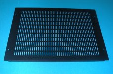
I advised the holed bottom and this cover (HIFI2000). A fan in the center of the lid on the inside will give much freshness. Congratulations for the work

Attachments
At load the DC rails are at 43V each.
Interesting. In NP's paper, the F5T V2 schematic specified a 32V rail voltage. However, in the V3, no numbers were given. I assumed (probably wrongly) that the required rail voltage is still 32 V. However, in the text of the paper, NP use an example of : 36 V secondary to give 48 V rail. However, in the PSU schematic, he still shows caps rated at 50V. So the question is, what should be the rail voltage be for V3? I suppose that higher the rail voltage, higher the output (provided the PSU can pump in more juice when needed).
Thanks!
Regards,
i expected it would be at a bit lower then 47VDC
I mentioned that it is 47V DC at no load earlier. Looks like I have to use a quite cooling fan mounted to the top cover to evacuate hot air from inside and also provide enough ventilation to the bottom cover to enable air flow.
- Home
- Amplifiers
- Pass Labs
- F5 Turbo Builders Thread