Buzz: It looks like you are gonna listen to a lot of heavy metal.
How good is the thermal interface between the heatsinks and the spreader? Do you use any goop or just bolts?
How good is the thermal interface between the heatsinks and the spreader? Do you use any goop or just bolts?
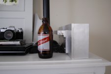
Here ya go. Rough idea. Times two should give about 7-8" in the bottom of the case. Enough for big trafo.
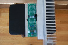
Here is current F5T V2 build. It is on similar, but slightly smaller heatsinks. THey are only about 16" deep x 6" high x 2 1/2" fin. As you can see, the fets are concentrated in the middle on a heat spreader. They are biased at about 400mV+, making bias about .85 to
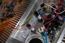
.9A per fet. The sinks are well within 10 second hot rule. Last I measured, they were 37C. Checked fets and they are a degree or two higher, so coupling is good. I haev nothig but silicon goop between spreader and sink. I feel like i could easily put another pair on these sinks. With the newer setup pictured above, I have deeper sinks with longer fins. Also the heat-spreader is couple inches longer, with big ol 1" section for mounting the fets. I will have four fets on 1 side and will consider dropping the diodes and biasing higher than 1A. Wish I could cram more on the sink, but oh well. Already have way more power than I need.
.9A per fet. The sinks are well within 10 second hot rule. Last I measured, they were 37C. Checked fets and they are a degree or two higher, so coupling is good. I haev nothig but silicon goop between spreader and sink. I feel like i could easily put another pair on these sinks. With the newer setup pictured above, I have deeper sinks with longer fins. Also the heat-spreader is couple inches longer, with big ol 1" section for mounting the fets. I will have four fets on 1 side and will consider dropping the diodes and biasing higher than 1A. Wish I could cram more on the sink, but oh well. Already have way more power than I need.
Attachments
Last edited:
Is the heat spreader needed
Buzzforb,
I am planning to build a F5 Turbo V2. I too have pretty much the same dimension heatsinks. 6 inches height and 8 inches deep. I would need to attach two of them to use it for one channel.
1. As V2 has two pairs, If we can stick each of the pairs on the different heat sink pieces, The heat sinks should dissipate the heat evenly. In such case I dont see the need of a heat spreader.
Under what reason does teh heat spreader act which is nesscary.
What is the material of Heat spreader. Is it Regular Aluminium. I guess copper can also be used for heat spreading I agree it is more expensive.
Thanks
Pandu
True. My layout did not allow for this. My fets were all bunched togetjer and i was unable to spread them. As long as you have adequate sinking, and the like pais are thermally connected to allow for good couplong, you should be fine. One advanatage of a spreader is the possibility, if correctly sized and mated, to distribute heat over greater surface area of the heatsink. In theory. The heat spreader looks like one gigantic fet to the heatsink. One solid sink is superior, but hard to find. From there, it is all about comprimises.
Heat spreader material
Buzzforb,
Thanks for your reply.
What is the thickness of the heat spreader.
What material is your heat spreader.
What precautions need to be taken to make sure the heat is transferred to heatsink
Did you weld the sinks together. As the heat spreader connects them together we may not need to weld them.
Thanks
pandu
Its 3/8" aluminum. The newer L shaped vetsion has 1/2" aluminum attached to the heatsink. I used silicon thermal grease to help with heat transfer. The sinks were not welded. Easy way yo check efficiency of heat transfer is with temp probe. Check fet, then spreader, then sink. You want them all close in temperature. The closer. The more successful you attempt.
What exactly don't you understand?
How to stuff it? ( I.E., component selection )
How to hook it up?
How to mount it?
Also, what amp PCB are you using?
")
Have you read this guide? http://www.diyaudio.com/media/build-guides/diyaudio-psu-build-guide-v1.0.pdf
How to stuff it? ( I.E., component selection )
How to hook it up?
How to mount it?
Also, what amp PCB are you using?
Have you read this guide? http://www.diyaudio.com/media/build-guides/diyaudio-psu-build-guide-v1.0.pdf
What exactly don't you understand?
How to stuff it? ( I.E., component selection )
How to hook it up?
How to mount it?
Also, what amp PCB are you using?
"How to stuff it?"
I don't want to do just have a list of items for me to solder on to the board. While that would be nice (if that's available) . I don't think I would be learning very much from it.
I'm planning on using the P-F5-2V20 from the DIYAudio store.
I have looked at that PDF. I'm looking at it again and SLOWLY going through it. I'll post if I have any questions.
Thanks for the help!
Last edited:
So reading this: Link
I have a few questions:
Thanks again for the help. I'll post more questions as I go.
I have a few questions:
- I can't seem to figure out the disadvantages / advantages of going with TO-247/TO-3P vs TO-220
- The BOM says "Capacitor Voltage Rating depends on your Transformer's Secondary Voltage rating". Now I can't figure what rating transformer I need. Is it 42v and 0.6v? I'm looking at the F5 schematics and I see this:


Thanks again for the help. I'll post more questions as I go.
The most important things to remember are -
Do the components fit the PCB mount holes, and also have no interference with each other?
Are the caps of big enough capacity and of a proper voltage rating?
Are the resistors of the proper value and wattage?
Does the component fit in the provided holes?
Are you planning on using a clip-on (or screw on) heatsink for the diodes, or mount them to the chassis? Do said heatsinks fit?
(Or will you just ignore the discrete diodes entirely and use a pair of bridges?)
There is a reason why fit is such a big deal - you will have a bazillion choices in manufacturer, value, voltage rating, etc... of the various components to use, and it will most likely work just fine. However, if something dosen't fit, it's a headache.
Hi alfa147x,
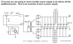
At the store site it has a Bom there ,for the boards,and I just go through the Power Supply and write those down to order them,In Nelson Pass articles he tells of a beefier supply to use,I've attached it for you,
If you decide you want some more power,you can go to 32v on the power supply,If you want more you will need bigger heat sinks or a fan or 2,and need to cascode the input fets,You can also remove the limiters and protection circuits ,but don't short the outputs and keep the thermisters they stabilize voltages on bias from the heat on the heat sinks,I hope this helps you some just go slow and If your stuck ask here,someone will answer!
Have fun!
NoSmoking
Attachments
Last edited:
- Home
- Amplifiers
- Pass Labs
- F5 Turbo Builders Thread