Hi audioSan,
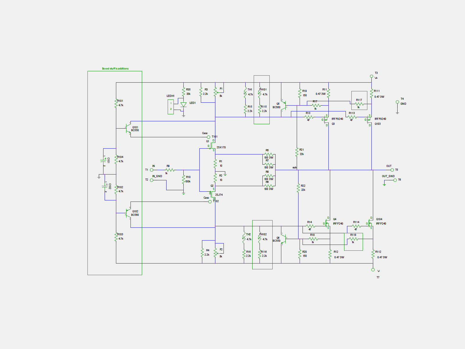
Thanks for the schematic,your right that's the one posted ,doesn't it show 2 .47R 3w per fet? and where does the r 105 and 108 go on the board?It show's 4 thermistors connected ,Thanks for your help !!!!!!!
I have 4r7 R101/104 it = 20 volts with 42+ - per rail,If I want more bias I need to increase the resistance on R104 and R 102 and should I change the value for value for P1 and P2 maybe 10K for both pots and R 104,R102? I have changed the source Resistors to 2 1R 5 W Per Fet in parrell to handle more wattage,
Thanks alot!
NS
it is 1 0R47 pr fet. 2 0R5 in parall is a good thing in the turbo
R105/R108 can be used insted of R5-R8.
there is room for 4 thermistors. but you only use 2. one spot or the other.
regarding R102/R104. they have nothing to do with bias. they are for J-fet voltage. you increase R101/R103 if you have higher rails
if you can't get the bias you want. you increase R3/R4.
Last edited:
here
C101/C102= 10uF
R101-R104= 4.75K for 21.5V cascode referance.
R101/R103= 10K R102/R104= 4.75K for 13.8V cascode referance.
Hi,
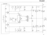
I've built the stock F5 (which sounds great) and have the store's boards for V2.0 of the F5c. I desire to run double MOSFETs and cascode the FETs with 34 VDC rails.
I have been following discussions on a couple forums, but remain confused (I'm somewhat of a beginner, so please be patient) as to whether someone has successfully built the F5c with double MOSFET outs and cascoding and then posted which resistors they had to modify (if at all) in order to have cascoding work well for them. When somone appears to have done so, it remains vague to me (perhaps out of ignorance) as to EXACTLY which schematic they are using after modification, if any.
If I have missed this somewhere, I apologize. Might anyone have suggestions regarding resistor choices for a full build and 32V rails using cviller's schematic and boards (schematic below)?
http://www.diyaudio.com/forums/blog...5-guide-pcb-version-2-f5_cascode_forguide.png
Thanks so much.
hello toxic. i have build F5 with dual outputs without cascoding.
but the cascoding is not that hard.
it is R101-R104 that neds adjustment according to your rail voltage.
formula is: rail voltage/(R101+R104)xR104.
so f.ex. 34/(4.75+4.75)x4.75=17V cascode referance voltage. wich is good.
but the cascoding is not that hard.
it is R101-R104 that neds adjustment according to your rail voltage.
formula is: rail voltage/(R101+R104)xR104.
so f.ex. 34/(4.75+4.75)x4.75=17V cascode referance voltage. wich is good.
for 1/3 of rail voltage you will have just above 10V. so still R26=10Kohm
but there is no problem to rise it to 16V. or higher.
Toxic,
It depends on the idss of the jfet you use. Read these posts of this thread, pages 14 - 16. If you use 10 ma idss jfet you may want to divide the voltage differently.
Rush
here's the schematic I used ,I removed the protection circuits ,so IF you don't use them don't short the speakers,,,,lol.
OK
schm from #290 is drawn by Mighty ZM for Vladimir ( and other Greedy Boyz)
there can't be any audible difference whatever size of cap you use across cascode biasing resistors - as long size of cap is above minimum value
regarding those other caps you mentioned previously - you're probably talking about caps in local rails decoupling ........
Hi Mighty ZEN,
I decided to remove them and let it play ,It's stable and running fine now I'm not changing it ,I will be putting it in a case and move on to a BA-1 ,When it's going then I can put the F5 to run the highs,a F5C to do mids ,and a Ba1 or Ba3 to run the bottom end,,,,I'm getting close ,
I would like to Thank you guys for all your help and posts,I wouldn't have it without your sharing!!!!!!Hey!!!!! Didn't you say you were dumb.lol....post 292 ,lol. Iwish I wuz as dunb as U,lol.
Last edited:
hello toxic. i have build F5 with dual outputs without cascoding.
but the cascoding is not that hard.
it is R101-R104 that neds adjustment according to your rail voltage.
formula is: rail voltage/(R101+R104)xR104.
so f.ex. 34/(4.75+4.75)x4.75=17V cascode referance voltage. wich is good.
Thanks so much for responding to my question concerning the voltage divider cicruit to the base of the cascoding transistor (with 34 volt rails and a total of 4 MOSFETs per board). It was that 16 to 17 volt range I was looking for. If that is what I should shoot for, then I can make adjustments with parallel resistors, if needed, and will probably simply use 10K and 10K to provide th 17 V. In addition, I have modified cviller's board so that I could place the 475 ohm R29 and R30 (from Nelson's schematic)before the base of the cascoding to prevent oscillations.
I am using matched 2SK170 and 2SJ74 for JFETs, and assume the cascoding transistor base voltage should be satisfactory, as another kind member cautioned me that the drain current on the JFET may require me to vary the voltage somewhat. (I am cascoding with BC550 and BC560).
Again, thanks to everyone who responded. I should have it powered up in a couple days.
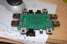
Here is single pair F5T on on of Ilquam's boards. USing all primo components. Used Mills as Rs instead of Fukushima, as I am still waiting. MP915 as feedback resistors, PRP 1W as Jfet Rrs, matched diodes and fets to 1mV. Will be listening to it and 2 pair F5t on TeaBag's boards being driven by B4 clone, hooked up to FAST system with Alpair 7.3 and Peerless XXLS in 80L box.
Attachments
Those are certainly weird looking feedback resistors. You say they will be replaced with Caddock MF915. The problem I has with the small Caddock packages is screw hole is smaller than #4, which is as small as I can reliably drill in the heatsink. However, an aluminium bar clamp works fine for all sizes of Caddocks.Here is single pair F5T on on of Ilquam's boards. USing all primo components. Used Mills as Rs instead of Fukushima, as I am still waiting. MP915 as feedback resistors, PRP 1W as Jfet Rrs, matched diodes and fets to 1mV. Will be listening to it and 2 pair F5t on TeaBag's boards being driven by B4 clone, hooked up to FAST system with Alpair 7.3 and Peerless XXLS in 80L box.
No. The Feedback resistors are MP915. They have a clamp heatsink on them. The output Rs will be replaced with Fukushima. Anything with a small hole and i got to clamp retention over screw.
What part number are those "clamp heatsinks". Do they attach to the main heatsink? I cannot tell much from the image.
I'll have to look it up. Here are some more pics. You can see the naked MP915's. There are heatsinks that come with predrilled holes as well. Got the Thermistors on the bottom and pressure will keep them on the heatsinks. I did not use the current limiters.
Attachments
Hi guys,
Need a little feedback....
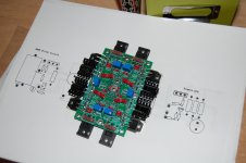
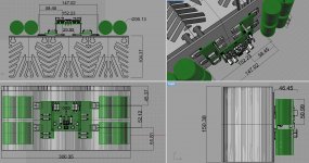
I Have a second set of heatsinks from my F5X build which i intend to use for a 2 pair F5TV3 ( or F5TV2 Cascode ? ) running at 32 V Rail voltage.
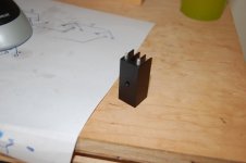
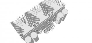
Issue is that they are 300mm X 150mm X 10 mm as pictures below.
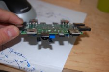
I redesigned Toecutter's PCBs to fit the space available 150mm width.
For that i put the power transistors and Diodes on separate boards connecting to driver board by copper standoffs.
Main worries are naturally spreading heat...so diodes ( which should run cooler than transistors...) are on the inside and Fairchilds on outside .
Would appreciate your opinions on viability of this solution .
Some images of proposed mounting arrangement...
Need a little feedback....
I Have a second set of heatsinks from my F5X build which i intend to use for a 2 pair F5TV3 ( or F5TV2 Cascode ? ) running at 32 V Rail voltage.
Issue is that they are 300mm X 150mm X 10 mm as pictures below.
I redesigned Toecutter's PCBs to fit the space available 150mm width.
For that i put the power transistors and Diodes on separate boards connecting to driver board by copper standoffs.
Main worries are naturally spreading heat...so diodes ( which should run cooler than transistors...) are on the inside and Fairchilds on outside .
Would appreciate your opinions on viability of this solution .
Some images of proposed mounting arrangement...
Attachments
If there is a way you can mount the diodes together, away from the heatsink, I think this would be best. I have been runnig a V2 for weeks and the diodes never even get warm. Subjecting them to the heat of the mosfets may equalize their temperature, but also introduces them to the possiblity of higher temps. by tying them together, you get farily decent temperature tracking, but avoid the heat. THeir performance is very much temperature based and I like the idea of keeping them relatively cool. THey will still be seeing the temperature inside the case, but this should be better than the heatsink.
Just my 2C
Very creative design, BTW
Just my 2C
Very creative design, BTW
Thanks for the input buzz but i have a question about the diodes, have you run them freestanding at the point they conduct heavily ?
Will they heat up a lot then...they should.
Is it that they run cool because they have a huge heatsink and at low amp power are not being stressed so are cool anyway ?
...or if i let them freestanding , away from heatsink, when they are put under pressure at high amp power / high dynamic peaks ...they will blow up ?
It's quite easy for me to mount them standing up between the top and bottom PCBs and get them away from heatsink, that is easy.
Last edited:
- Home
- Amplifiers
- Pass Labs
- F5 Turbo Builders Thread