F5 turbo
Hi chchyong89,thank you for replied.I will looking for a group buy.
I sent my layout for fabrication. Try paying attention this thread, maybe someone will run a group buy
Originally Posted by arche13
f5 turbo version 50w 8 ohm, what case hifi2000 4u 400mm heavy is enough? Or which version of case in silicon ray?
Thank you jacco
5U 500mm.
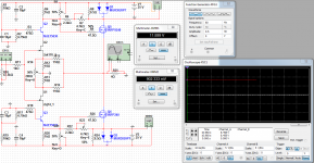
May someone help me finding out what is going wrong with the following simulation?
The models I used are:
2sk170:
+Beta=59.86m Rs=4.151 Rd=4.151 Lambda=1.923m
+Vto=-.5024 Cgd=20p Pb=.4746 Fc=.5
+Cgs=25.48p Is=8.477p
+Kf=111.3E-18 Af=1
2sj74:
+Beta=92.12m Rs=7.748 Rd=7.748 Lambda=4.464m
+Vto=-.5428 Cgd=85.67p Pb=.3905 Fc=.5
+Cgs=78.27p Is=12.98p
+Kf=26.64E-18 Af=1
Thanks in advance
Attachments
Last edited:
May someone help me finding out what is going wrong with the following simulation?
...
Thanks in advance
My first guess is that the potentiometers with Key=B and Key=D are improperly adjusted. Perform the adjustment steps outlined in the F5 Manual: http://www.firstwatt.com/pdf/prod_f5_man.pdf
Daniel,May someone help me finding out what is going wrong with the following simulation?
The models I used are:
2sk170:
+Beta=59.86m Rs=4.151 Rd=4.151 Lambda=1.923m
+Vto=-.5024 Cgd=20p Pb=.4746 Fc=.5
+Cgs=25.48p Is=8.477p
+Kf=111.3E-18 Af=1
2sj74:
+Beta=92.12m Rs=7.748 Rd=7.748 Lambda=4.464m
+Vto=-.5428 Cgd=85.67p Pb=.3905 Fc=.5
+Cgs=78.27p Is=12.98p
+Kf=26.64E-18 Af=1
Thanks in advance
Check the orientation of Q5 it may be installed inverted.(I have the same problem)
Best Regards
Jim
Daniel,
Check the orientation of Q5 it may be installed inverted.(I have the same problem)
Best Regards
Jim
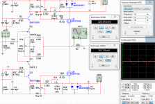
Yup, you spotted the real problem.
Jim, you got it right!
Ihquam, thanks for the answer also!
I lost the whole day checking it but couldn't find the problem...
That's why NP Citation 12 wasn't working also.
Besides IRFP240, 2SJ74 and MJE15031 were also inverted.
Now I can bias it, but I need 30V at input to produce 500mV at output. Perhaps the JFET models are problematic? Jim, what models are you using?
Attachments
Jim, you got it right!
Ihquam, thanks for the answer also!
I lost the whole day checking it but couldn't find the problem...
That's why NP Citation 12 wasn't working also.
Besides IRFP240, 2SJ74 and MJE15031 were also inverted.
Now I can bias it, but I need 30V at input to produce 500mV at output. Perhaps the JFET models are problematic? Jim, what models are you using?
Your wiring to the base of cascode transistor Q3 is wrong. R18 is connected to ground, not the voltage from the resistor divider.
Thanks for finding it out, Ihquam!
Besides that I also had to change 2SK170 by Multisim original model and 2SJ74 by 2SJ108 original model too, because the models I was using didn't work at all. I had to have very large input levels.
What about R19? I was using 10k because I thought it should be symmetrical with upper side, but I've just noticed it is really 47,5k on schematics, while R1 is 10k. What's the right value?
 just now i stumbled over this, from F5 turbo article
First off, you get the 44 amps. In addition, with Fets you get an output stage
that will deliver more Class A power at a given bias figure due to the square
law character of the Fets. Unfortunately you also tend to get a thermally
unstable circuit that is prone to bias hogging. This is true of Vertical Mosfets
and even more so with Bipolar transistors. There are a couple of examples of
high end amplifiers on the market which boast no ballast resistance, but the
praise for their sound is accompanied by rumors about reliability.
As an alternative, you can consider carefully matched Lateral Mosfets which
have a declining temperature coefficient. Unfortunately they tend to have
lower current ratings, and so are not suited to this particular goal.
May someone help me finding out what is going wrong with the following simulation?
can I ask why you show schematic using cascoded jfets, with only 25V rails
Does anyone have SPICE models for FQA28N15 and FQA36P15 ?
Isn't the input capacitance too high on these?
FQA36P15
2550typ
3320max
pF
FQA28N15
1250
1600
pf
FQA19N20c
830
1080
pf
FQA12P20
920
1200
pf
Isn't the input capacitance too high on these?
FQA36P15
2550typ
3320max
pF
FQA28N15
1250
1600
pf
FQA19N20c
830
1080
pf
FQA12P20
920
1200
pf
I bought 25 each of FQA36P15 and FQA28N15 because of the apparent unavailability of FQA19N20c and FQA12P20.
Where can one obtain FQA19N20c and FQA12P20?
- Home
- Amplifiers
- Pass Labs
- F5 Turbo Builders Thread