Well this is simpler. If I want to send 40 amps max with a 40 Volt DC source, then I'd use a 1 ohm resistor.
If the capacitance is 400,000 uF (0.4F) the time constant will be 0.4 seconds, and at 2 seconds the amp is ready to rumble.
The max power dissipated across the resistor will be 40x40 or 1600 watts, but will last for a very short duration.
This looks unreasonable to me, but I don't know how long this power dissipation has to last before the resistor blows up.
How quickly will the relay switch.
You have 20R, how many Amps will that conduct? 110/20 is around 5.5A?
I am using this circuit in F5T V2.
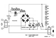
Are not 20R, 40R are. It's fast, I'm using the relay Siemens D0721 V23154 F104, connects in less than 1 second, very soft.
This circuit came in 2001 Elektor magazine.
I made this simple circuit on startup, is simple and works great.
this Circuit is acctualy the same as the softstart that jim's audio is selling.
Soft Starting Switch Full Kit for Power Amplifier | eBay
this Circuit is acctualy the same as the softstart that jim's audio is selling.
Soft Starting Switch Full Kit for Power Amplifier | eBay
In this circuit heats anything, which is good because the CL-30 warmed up a bit.
This circuit originally released in Elektor, but the Chinese copy / paste everything.

An externally hosted image should be here but it was not working when we last tested it.
If you adopt the dual purpose soft start and slow charge by inserting a resistance in the primary then you must use a long time delay.
If you adopt that long time delay then the consequence is resistor overheating.
But the basic problem is that a primary resistance is not effective in limiting the secondary current.
If one adopts a combination of high resistance Power NTCs to avoid the resistor overheat risk, then you will find that the secondary current limiting is even less effective, due to the large reduction in resistance of the now hotter NTCs.
It seems that my message is not getting through.
Would you all start thinking and if necessary measure the effectiveness of your slow charge proposals and report here to prove me wrong. I am sure there are many who would love that outcome and an apology from me for misleading the whole community.
There's the challenge. Prove that added resistance in the Primary is effective in limiting the charging current of the capacitors in the secondary circuit.
measure the effectiveness.
Don't try to simulate the ultra complex interactions of temperatures and Starting Transformer with varying resistances and varying emfs with varying capacitor charge.
Look at some of Gootee's simulations for the steady state PSU capacitance AFTER the added resistor has been bypassed to get an inkling to the complexity involved.
Hey, the F5 turbo V1 im trying to find out how much more heatsink is needed ?
i was going to use the 4U case here for the Standard F5
modushop.biz
How would that do do you think ?
i was going to use the 4U case here for the Standard F5
modushop.biz
How would that do do you think ?
measure the effectiveness.
Don't try to simulate the ultra complex interactions of temperatures and Starting Transformer with varying resistances and varying emfs with varying capacitor charge.
Look at some of Gootee's simulations for the steady state PSU capacitance AFTER the added resistor has been bypassed to get an inkling to the complexity involved.
Andrew, you are saying measure Amps running through the primary using a softstart? I would like to measure it if I can. Do I need anything more than a digital Multi Meter? You are saying that a CL30 on the primary is not that effective, and should be on the secondary?
A 4U is OK for the standard F5, but I would use a 5U for the F5T.
Also make sure you use at least the 400mm model. The 300mm will not have enough disappation because the fins on their heatsinks are just not long enough to handle all the heat.
To give a comparison: on my KSA50 clone I use heatsinks on each side that are 200mm tall and are 510mm deep. The extrusions has a solid area that is 16mm thick and fins that are 60mm, and are spaced 13mm apart. Each fin taper from a root of 5mm to tip of 1mm. The KSA50 is biased at the moment to deliver 55W into an 8R load and I can keep my hand on the sink for only 15secs.
- Home
- Amplifiers
- Pass Labs
- F5 Turbo Builders Thread