This also an exercise for me to learn and for fun vs. a definitive answer. I welcome corrections / additions.
2 N and 2 P boards per channel...
0V370 (if you had 0.370mV, that'd be pretty pitiful)") across 0R5 (I think the test points measure the equivalent of the points across both source resistors in parallel for each output device. So, 0A740 per vertical set. 4 Vertical sets per "phase". 4 Ns and 4 Ps. => ~3A => 6A of "Class A current" before we go klunk with push/pull.
across 0R5 (I think the test points measure the equivalent of the points across both source resistors in parallel for each output device. So, 0A740 per vertical set. 4 Vertical sets per "phase". 4 Ns and 4 Ps. => ~3A => 6A of "Class A current" before we go klunk with push/pull.
Rails +- 48 less ~4Vish in loss => +- 44V => running balanced / differential => 88Vp => 176Vpp => ~62Vrms before voltage clipping.
Into 8R you're going to go klunk before you hit the rails.
6A gets you to ~290W into 8R
I screw this up ALL the time.... so, someone will likely be along momentarily to fix my errors. BUT... that does seem to agree pretty well with the article... So, I've got that goin' for me... which is nice.
Edited to fix some silly autocorrect... LOL!
2 N and 2 P boards per channel...
0V370 (if you had 0.370mV, that'd be pretty pitiful)
across 0R5 (I think the test points measure the equivalent of the points across both source resistors in parallel for each output device. So, 0A740 per vertical set. 4 Vertical sets per "phase". 4 Ns and 4 Ps. => ~3A => 6A of "Class A current" before we go klunk with push/pull.Rails +- 48 less ~4Vish in loss => +- 44V => running balanced / differential => 88Vp => 176Vpp => ~62Vrms before voltage clipping.
Into 8R you're going to go klunk before you hit the rails.
6A gets you to ~290W into 8R
I screw this up ALL the time.... so, someone will likely be along momentarily to fix my errors. BUT... that does seem to agree pretty well with the article... So, I've got that goin' for me... which is nice.
Edited to fix some silly autocorrect... LOL!
Anyone?I have a question regarding this section in the article:
Is there a "rule of thumb" when parallel J-Fets are recommended? Currently running the amp with 4 output pairs per side (Toshiba 2SK1530 / 2SJ201 which seem to have higher capacitance than the Fairchild parts).
Many Thanks
Sven
Many Thanks
Rule of thumb is that each pair of BL JFETs are sufficient for 2 or 3 pair output. More than that is better served with more devices.
As you add more input (or output) devices in parallel, the open loop gain drops a bit because the drain resistance has to become smaller for the same Vgs, and more pairs also require less Vgs. The gain of the first stage is approximately drain resistance divided by source resistance. This is slightly offset by the increased transconductance of the (bigger) output stage.
Best to put it on a sim, but if you have no problems with 4 pairs and a single input pair, you should stick with it.
What would be the best approach for adjusting P3 on a balanced F5T with connected feedback loops - feed a symmetrical signal into the amplifier and measure/adjust distortion for each "half channel" output vs. ground, trying to get similar distortion characteristics for both halves? Or is it better to "separate" both halves prior to adjustment by grounding the feedback loop...
Thanks
Sven
Thanks
Sven
Last edited:
What would be the best approach for adjusting P3 on a balanced F5T with connected feedback loops
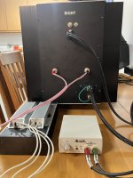
I don't know if this is the best way to adjust P3, here is how I did it on mine. The Akitika 2ppm 1K sine wave generator has a cable with two RCA's going into the XLR (Amazon under $10 USD) which feeds the amplifier XLR input. The amplifier speaker output to an 8 ohm load, which then feeds a voltage divider to a Behringer UM 2 sound card. The sound card has a USB output to my laptop with REW software for FFT.
BEFORE I connect the sound card/voltage divider to the 8 ohm load, I adjust the Akitika for 2.83vrms into the 8 ohm load. This gives the 1 watt output into 8 ohms.
The voltage divider is set to output 1 vrms into the sound card, any more than that could fry the soundcard (did that once). Building the voltage divider is lots cheaper than buying soundcards.
Since there are two P3's to adjust, I have a note pad to record which P3 I adjust and how much (quarter turn, half turn) and which direction (CW vs CCW). It keeps me from getting lost with these adjustments. It is possible to get 2nd order distortion, just beware the adjustment can be positive 2nd order or negative 2nd order. REW FFT software shows the phase angle for 2nd, 3rd, 4th, etc.
It took me a full day to adjust, 2 hours to get the amps to operating temperature, and usually 15 - 30 minutes to stabilize after each adjustment.
The 2 hours to get the amps temperature stabilized is from the FirstWatt F5 owners manual.
Attachments
- Home
- Amplifiers
- Pass Labs
- F5 Turbo Builders Thread