nope
if we are thinking about same cap
Thanks Zen Mod!
That would be C3/C4 with value around 1nF.
I will add it to the boards before continuing.
( Need to complete some other work tonight, then back the F5T -- I did a massive rewiring job on it.... for the better???? we'll see. ).
")
BigE, there's probably no need but I put 1nf into all 4 boards (C3/C4). I did it as extra insurance against oscillation. (I sleep better) One nf or two isn't going to reduce the bandwidth any appreciable amount. Sleep is important!
TJ
I shall do this shortly. At the moment, I am embroiled with getting an active speaker system equalized -- and adding a tweeter. It's a bit slow going.
As you wrote earlier: I wouldn't worry too much about the 100R from emitter to drain either, unless you find you have an oscillation issue and it can't be resolved by increasing C3 & C4 or increasing output gate stoppers.
Right now, they are the standard 47.5 ohm. What value would you suggest? Would adding a very small inductor help to block the oscillatory frequencies?
When I fire this up next, I will take a look at the outputs on a scope to ensure that there actually is *some* oscillation. I should be able to see something. Recall, oscillation is suspected because the biasing output offset is very different with and without shorting plugs in place. ( Some 300 mV ).
Last edited:
I recently bought F5 turbo pcb's (DIY Audio genuine) from someone, they are un-populated. When I got the boards I realized that I have 3 p channel boards and 1 n channel boards. I'm guessing this is irrelevant and that I can just change a p channel into an n channel and make sure the supply voltages and arranged appropriately.
I'm I correct?
I'm I correct?
In trying to finish this, I've run up against a problem... VAC on the positive rail.
The amp power has been *completely* rewired since last year.
Circuit changes: Tea Bag's power supply boards have has the snubber resistors and caps added. Transformer snubbers were removed. The bleeder resistors on the power supply work.
The transfomer secondaries are 30-0-30, with rails at +41.5 and -41.5 VDC.
However, reading with an ohm meter shows that there is 91.5 VAC on the positive rail! 0 on the negative.
There are no shorts from the diodes to the case. I even replaced with MICA insulators to test. Only the right channel is powered, the input and output boards are not connected. ( Thank goodness. )
I cannot imagine what can be causing this. This is true whether or not the 0 volt line on the secondary is connected to the ground lift. ( The way I read the power supply schematic, the ground lift diode bridge/CL-60 creates the audio ground. )
Does anyone have an idea where I can look? I'm a bit nervous about turning it on.
Last edited:
Check that the body of the transformer is properly insulated from the case.
Thanks nasnbap,
The transformer is an encapsulated Plitron toroid. It is mounted on a backplane to allow for wires to run underneath it. There is no short turn.
The left channel is identical. It has a separate diode bridge from the right channel, fed by different secondaries
It too has 91.5 VAC on the positive rail, 0 VAC on the negative rail with both rails showing 41.5 VDC
There is a second transformer in the cabinet that is used to power other circuits, like the speaker protection, as well as some relay logic that makes sure the thermistor feeding the capacitor banks is allowed to cool when power is cut and restored.
The secondary transformer and it's diode bridge was moved away from the Front end boards and closer to the front of the enclosure.
This meant it's primary side leads needed to be extended.
I used 20 gauge teflon coated because it's a low draw. I will change that wiring to something bigger.and ensure that is not a hazard..
Last edited:
The left channel is identical. It has a separate diode bridge from the right channel, fed by different secondaries
It too has 91.5 VAC on the positive rail, with both rails showing 41.5 VDC
A schematic with and changes you made exactly like you built it might be helpful as well as some detailed pictures. Also you might want to simplify for testing, if you haven't already, disconnect the other transformer and any extras you have going there and test the supply to the rails again. If it's still got the AC, you ruled out a bunch of stuff and the other TF. I don't know that much about this stuff, but I do know troubleshooting is always easier with less stuff in the circuit.
Last edited:
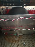
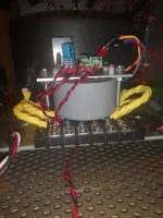
Is this a problem? The terminal strip on the bottom is where the main amp secondaries are located. The grey can is the second transformer, right above them. The twisted black/red are regulated 12 volt lines to the speaker protection and relay logic. The yellow are the secondaries from the main transformer. They connect to the terminal strip.
This is the furthest inside the box that 120V goes. On the primary side, 120 goes to a terminal strip, where the primary connections are configured to give 30-0-30. This is a 5 channel 2KVA multivoltage toroid, only 4 channels are being used, and the toroid has been wired as if a 240 Volt line was connected, which gives the lowered output voltages. It was being used to provide balanced power to line level gear.
Ironically, the project was partially motivated to get rid of the toroid. I've since bought more outputs than the toroid was worth.
As you can imagine, Space is very limited in the box.
Attachments
Last edited:
Are you measuring 91.5vac from the DC common point to the + 41.5 volt output of the power supply? How do you have the chassis ground connected to the power line ground and how is the chassis connected to the DC common?
I would check your meter to make sure it is OK. If you have a second meter try comparing the 2 meters for this measurement.
Assuming that you do not have a meter problem or a wiring issue with the transformers, I would start by disconnecting that second transformer completely from the power line. Simplify the circuit until you find out where this AC reading is coming from.
- Home
- Amplifiers
- Pass Labs
- F5 Turbo Builders Thread