all N's pr ch must be matched. and all P's pr ch must be matched.
I understand that on Q1 Q2 Q7 Q8, but doesn't P1 and P2 control the bias on Q3 and Q5, if so, then is matching needed. It's been a long time guys and I'm not sure if I'm reading the circuit correctly. I probably have it wrong, but I'm here to learn!
Enlighten me...
Thanks
JT
Last edited:
I understand that on Q1 Q2 Q7 Q8, but doesn't P1 and P2 control the bias on Q3 and Q5, if so, then is matching needed. It's been a long time guys and I'm not sure if I'm reading the circuit correctly. Probably not!
Enlighten me...
Thanks
JT
Unmatched mosfets: The amplifier "bias hogs" and one mosfets bias runs away and amplifier catches on fire.
Unmatched Jfets: Some mismatch can be compensated for with P3, but you will never be able to achieve as low of harmonics as with matched jfets. But amplifier works. And you lose sleep at night over this knowing the amplifier is not as good as it could be.
Okay then, matched it is.
 Thanks for the input!
J
Matched
I made a quick test rig for the fets and all were 3.33-3.34V that is all except one which I had set aside to use. (I bought extra thinking maybe V3 later) Anyway, one of the ones I had marked for this install was 3.37. Mr. Pass said to keep them within 30mV @ 5mA, so thanks, I would have been out of spec.
On to stuffing some boards....
I'm going hit you with a lot of, mundane, questions and hope for tolerance. Snarky is okay, as long as the answer is included with the snark.
I made a quick test rig for the fets and all were 3.33-3.34V that is all except one which I had set aside to use. (I bought extra thinking maybe V3 later) Anyway, one of the ones I had marked for this install was 3.37.
Mr. Pass said to keep them within 30mV @ 5mA, so thanks, I would have been out of spec. On to stuffing some boards....
I'm going hit you with a lot of, mundane, questions and hope for tolerance. Snarky is okay, as long as the answer is included with the snark.
Last edited:
I sure wish the board holes were more than 8cm.... thinking about looking for another solution, that's not even 20 gauge wire.
The solution is to just to take your 14AWG (or whatever size) wire and cut some individual strands off it.
The solution is to just to take your 14AWG (or whatever size) wire and cut some individual strands off it.
Correction: on the my .8mm to cm conversion...
I understand you can hack the wire and do a quasi legit solder bridge to gain more contact, but...
On the other hand, the pads are large enough to think of other options, so I will give it some thought. Size does matter...
Last edited:
Need clarification...
I'm been looking at the circuit for a few days trying to make sure I understand what's going on. I've run across something, that has me scratching my head.
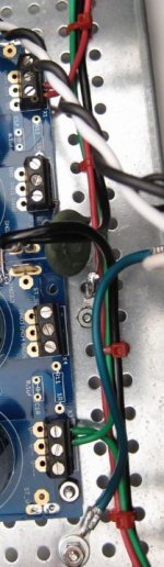
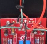
In 6l6's build guide for Turbo and PSU see photos:
We have the green,black,red from the supply out:
Green V-
Red V+
Black Star ground
FE Board input we have:
Green to G
Red Ve+
Black Ve-
Would someone clarify for me please.
Thanks
I'm been looking at the circuit for a few days trying to make sure I understand what's going on. I've run across something, that has me scratching my head.
In 6l6's build guide for Turbo and PSU see photos:
We have the green,black,red from the supply out:
Green V-
Red V+
Black Star ground
FE Board input we have:
Green to G
Red Ve+
Black Ve-
Would someone clarify for me please.
Thanks
Attachments
Last edited:
I understand you can hack the wire and do a quasi legit solder bridge to gain more contact, but...
I use a trick I learned from ZenMod: take the largest resistor lead that will fit in the hole, spiral wrap one end of it around your 18AWG (or whatever) and solder. Then solder the other end into the PCB hole.
I use a trick I learned from ZenMod: take the largest resistor lead that will fit in the hole, spiral wrap one end of it around your 18AWG (or whatever) and solder. Then solder the other end into the PCB hole.
That's a great idea and something I was thinking about like using a header. Thanks for the tip.
Need clarification...
I'm been looking at the circuit for a few days trying to make sure I understand what's going on. I've run across something, that has me scratching my head.
In 6l6's build guide for Turbo and PSU see photos:
We have the green,black,red from the supply out:
Green V-
Red V+
Black Star ground
FE Board input we have:
Green to G
Red Ve+
Black Ve-
Would someone clarify for me please.
Thanks
Anyone, 6l6?
I sure wish the board holes were more than 8cm.... thinking about looking for another solution, that's not even 20 gauge wire.
...take the largest resistor lead that will fit in the hole, spiral wrap one end of it around your 18AWG...

Solder bucket, turret & pins are useful, form the wire into a J hook and solder it around the turret.
Last edited:
I use a trick I learned from ZenMod: take the largest resistor lead that will fit in the hole, spiral wrap one end of it around your 18AWG (or whatever) and solder. Then solder the other end into the PCB hole.
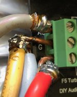
I amp using 14 guage romex wire to wrap the ends of large secondary wires to fit into a screw block.
See attached.
Rush
Attachments
I did something really weird -- I wired the boards with thin wires. Since I have 4 boards in a channel ( two per polarity ), these are wired *in parallel*.
Can't say that it is working yet though. Once the wiring of the power distribution was completed, it was summer and too hot to work on. Seems to be cooling down a bit now though. Should be back to it soon.
Can't say that it is working yet though. Once the wiring of the power distribution was completed, it was summer and too hot to work on. Seems to be cooling down a bit now though. Should be back to it soon.
Solder bucket, turret & pins are useful, form the wire into a J hook and solder it around the turret.
I did that once with a PCB mounted "solder cup", but was forced to drill out the small holes to make them fit. I cannot find anything with a 20 awg pin.
@BigE
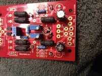
I drilled them out as well, The pads are big enough to do so, I read where the holes were intended to be larger, but the mistake wasn't caught. The fear was that drilling them would cause a pad to rip, or come loose. I used a high speed drill and very little pressure. It worked like a champ and thee is no need for wire trick, or header pins etc. All the holes except the gate were drilled to accept up to 14 gauge wire.
This is after the first hole drilled, see the one ground hole which is larger. Sorry for the blurry photo.
Attachments
- Home
- Amplifiers
- Pass Labs
- F5 Turbo Builders Thread