")
It looked on the scope that the hum had diminished. Then I noticed that the shorting plugs were not in place....
...... Do NOT plug in a shorting plug with the amp on. I am sure I've done it before, but this time, I heard two pop pop and the fuse blew. I think the last time I did it, I had a shorting plug that makes ground before signal....
Obviously I did this before I put in the rail fuses.... Testing with a DMM showed one N channel and one P channel mosfet shorted from Drain to Source.
I think the concern of the rail fuse blowing is a red herring. Because if there is no fuse, then the mosfet blows and you get full rail to the speaker anyway.
At least if there is a rail fuse, you're not replacing output transistors. And if you have speaker protection, all it well.
When NP says matching is not all that important betweem MOSfets, is he refering to the match between N and P?
It seems that you need to have all outputs in a single channel of the same polarity matched. Is that right?
Omg... The right answer...for 40 V rail biasing MOSFET for .6A, power across MOSFET and src resistors is 24 watts. O.18 watts by src resistor. 23.82 watts across mosfet. Effective resistance if MOSFET is 23.82/(0.6x0.6) = 66.16666 ohms.
It's not about resistance.
That quantity varies with power output (or gate input voltage, if you choose to look at it like that). Resistors on the other hand have a fixed resistance that does not vary with current (ideal situation).
The source resistor has to pass the full load current if no diodes are used. If diodes are used, the resistor has to handle about 2A or so. For 0.5 ohm resistors, that's about 2 watts, so two 3W resistors will do the job. they will run quite hot though.
Keep in mind that with music the average power output is much less than the peak value. You may have 2 amp peaks in each output transistor of a V3 when putting out a lot of power into 4 ohms but the average power will usually be about 1/10 of that value. So the resistors do not run hot when playing typical music over normal speaker loads.
Keep in mind that with music the average power output is much less than the peak value. You may have 2 amp peaks in each output transistor of a V3 when putting out a lot of power into 4 ohms but the average power will usually be about 1/10 of that value. So the resistors do not run hot when playing typical music over normal speaker loads.
While this is true, in a Class A amplifier the minimum current the source resistor will pass is the standing current/bias current.
For a F5T V3 biased at '350mv' (I find voltage-led bias a bit misleading), this equates to about 0.25W. For a standard 3W ceramic, thermal resistance is approx 90C/W - meaning with 0.25W dissipation, temperature rise will be ~24C above ambient. At 40C ambient (typical for this kind of an amplifier) the resistor body will be above 60 degrees.
60 degrees is very hot to the touch. Resistor will be well within safe limits, but I stand by the statement that it will be hot. 1/4W doesn't look like much, but when you touch it, you will know it. If you look at the original F5, it required a 6-7W resistor to keep temperatures tolerable and even then the resistor would run at 90 degrees.
A feature of Class A is that the power used at full Class A operation is the same as that used at idle. Here is the proof using an AC signal.
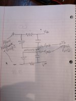
Assume rail voltage is 40 volts, and the bias at idle is 0.6 A, power is 24 watts.
The equivalent DC voltage and current necessary to generate the same power ( ie heat ) using a sine wave with max amplitude being peak across both N and P channels is the RMS Voltage and Current.
The RMS voltage of a sine wave with 40 V peak amplitude = 40/sqrt(2) = 28.28427125 Volts RMS.
The RMS current for a sine wave at 1.2 amps peak amplitude = 1.2/sqrt(2) = 0.848528137 A RMS.
Assuming they are in phase, RMS Power = Irms * Vrms = 0.848528137 * 28.28427125 = 24 watts.
Which is identical to the heat transfer at idle for each P and N channel device.
So, how much power is being made by one MOSfet at peak?
At peak, V = I(Rm+Rs) or 40 = 1.2(Rm +0.5) Solving for Rm gives, Rm = 40/1.2-0.5 = 32.83333333 ohms.
At peak one device is off, the other is generating P=i^2*R = 1.2*(1.2* 32.83333333) = 47.28 watts, with V = 39.4 (= 40V - 0.6V )
The max current across the source resistors is 1.2 Amps, which gives max power = 1.2*1.2*0.5 = 0.72 watts, or 0.36 watts across each of the pair. Note that this assumes no diodes are conducting -- when diodes conduct, the current across the source resistors will decrease.
While this is true, in a Class A amplifier the minimum current the source resistor will pass is the standing current/bias current.
For a F5T V3 biased at '350mv' (I find voltage-led bias a bit misleading), this equates to about 0.25W. For a standard 3W ceramic, thermal resistance is approx 90C/W - meaning with 0.25W dissipation, temperature rise will be ~24C above ambient. At 40C ambient (typical for this kind of an amplifier) the resistor body will be above 60 degrees.
60 degrees is very hot to the touch. Resistor will be well within safe limits, but I stand by the statement that it will be hot. 1/4W doesn't look like much, but when you touch it, you will know it. If you look at the original F5, it required a 6-7W resistor to keep temperatures tolerable and even then the resistor would run at 90 degrees.
A f5 V3 has 2- 3 w source resistors in parallel for 6w so the temperature rise would be 1/2. Hot is a relative term and certainly 24c or actually 12c above ambient is not hot for a power resistor. Yes, bias voltage is a misleading term unless it is in reference to Vgs. Source resistor voltage is not bias voltage but it is a commonly used term in DIY where you are measuring source resistor voltage to determine bias current.
Biasing at a source resistor voltage of 350mv with the diodes installed is not going to happen for me. It’s just too close to the conduction point for the diodes and with 4 pairs of outputs the power gained is not worth the risk for typical speaker loads.
- Home
- Amplifiers
- Pass Labs
- F5 Turbo Builders Thread