you said no 50Hz hum and posted a no input measurement of 0.3mVac to 0.4mVac.I will do that, but i think that's not the problem. when i have my amp conected to my 89db tannoy sensys, i can hear the buzz or hum.
Now you are saying you hear it through your Tannoys.
Which?
Now add a link across two diagonal tabs and include a turn through which the securing bolt will pass. That bolt and this first shorting link become the Chassis connection.I can't quite tell how you have your ground loop breaker hooked up, especially the black wire. Below is how I setup mine, ESP style.
BK
Add an insulated link across the two diagonal tabs that are still empty.
Connect one of these tabs to Main Audio ground.
As a final step add a switch across two adjacent tabs. That becomes the Disconnecting Network defeat switch.
BTW,
you don't need a power resistor.
The volts drop across the paralleled diode when fault current passes is too low to damage the resistor.
you said no 50Hz hum and posted a no input measurement of 0.3mVac to 0.4mVac.
Now you are saying you hear it through your Tannoys.
Which?
that's what happens when you are doing 3 things at the same time including baby sitting

i have ALWAYS the 50hz hum. input shorted or not. That's why i ear it on the tannoys. Sorry for my error.
I wasn't too clear, but I was asking about Joca's GLB in his humming F5 chassis pic. Mine is already installed in my M2 and VFET and seems to be doing its job. I believe that I simply followed the ESP diagrams, but your suggestions are interesting and clever.
BK
BK
Now add a link across two diagonal tabs and include a turn through which the securing bolt will pass. That bolt and this first shorting link become the Chassis connection.
Add an insulated link across the two diagonal tabs that are still empty.
Connect one of these tabs to Main Audio ground.
As a final step add a switch across two adjacent tabs. That becomes the Disconnecting Network defeat switch.
BTW,
you don't need a power resistor.
The volts drop across the paralleled diode when fault current passes is too low to damage the resistor.
As a final step add a switch across two adjacent tabs. That becomes the Disconnecting Network defeat switch.
didn't understand this step. don't know what a network defeat switch is. i've searched.
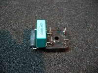
the cap in the picture is a 100nf ?
thank you for your time and patience
Last edited:
didn't understand this step. don't know what a network defeat switch is. i've searched.
the cap in the picture is a 100nf ?
thank you for your time and patience
Different strokes for different folks. Many/most are happy with the CL60 GLB. I opted for the ESP type outlined here in fig. 4 and used parts I happened to have on hand. Not saying it's better or it will help your situation, but I noticed that you seem to have wired yours a bit differently.
BK
i have the CL60 GLB but i may have wired it incorrectly. i will try the ESP type and remove the CL60
What's the thing on the right circled in yellow??
BK
Attachments
You have a choice between two methods of making the ClassI amplifier safe for operation.didn't understand this step. don't know what a network defeat switch is. i've searched.
the cap in the picture is a 100nf ?
thank you for your time and patience
Connect all the exposed conductive parts direct to the protected Chassis.
Or
Use a Disconnecting Network (DN) that can pass Fault Current from Main Audio Ground (MAG) to the Chassis.
If one make that choice and install it in the completed amplifier/project, then you can't change it later.
However if you adopt the DN methodology and add a switch across the DN you can keep the switch open to make the DN effective. On closing the switch you bypass the DN and the MAG is directly connected to Chassis. You can choose open or closed after building.
That switch could be called a Disconnecting Network defeat switch. That's the first time I have used that phrase. I would not expect Google to find any earlier occurrence.
Finally, you will see some DN which show all the options. Just look for them.
You need the Power Diodes to pass the Fault Current.
The optional parts are:
A capacitor
A resistor
A Thermistor
A switch.
Some diagrams show all 5 items.
Last edited:
OK, You need to find out why your amp channels are humming.that's what happens when you are doing 3 things at the same time including baby sitting
i have ALWAYS the 50hz hum. input shorted or not. That's why i ear it on the tannoys. Sorry for my error.
Let's not take it apart yet.
Short both inputs with zero ohm shorting plugs. Power ON.
Measure the output H+N using the 199.9mVac scale on your DMM.
Post the results.
i've made those measurements when a single channel was shorted. didn't try with both shorted. The short was made on a rca plug with a wire shorting the internal conectors. The initial result was 0.5-0.6 mvac. i could only reduce it by tightening the bolts in the ixys heatsinks. With this change i've measured 0.3-0.4mvac with only one input shorted. Never shorted both while measuring. this result didn't change, not even when the ixis diodes were separated from the cap bank pcb, and put close to the toroid transformer, one each side. i tried to rotate the transformer and nothing happened.
tomorrow i'll test with both inputs shorted.
tomorrow i'll test with both inputs shorted.
with both inputs shorted (0.3ohm plugs) i have 0.4-0.5mvac. the hum is audible when my ear is 5cm away from the speaker. for now my speakers are 89db but in a month or two they will be ~96db. this is the main reason why i am pursuing this noise reduction. also, don't know if this T+N noise in the uper frequencies can affect the sound
not generating any signal from arta
not generating any signal from arta
An externally hosted image should be here but it was not working when we last tested it.
I too find that close up (50mm) that I hear ~0.3mVac of Hum at the speaker terminals with normal sensitivity speakers.
That is why I consider that value as an absolute maximum for a completed amplifier in it's final enclosure and wired up. Fortunately most finalised builds end up with <0.1mVac of H+N
If you plan to go to 96dB speakers, I think you will have to adopt much less hum and less noise as well.
That is why I consider that value as an absolute maximum for a completed amplifier in it's final enclosure and wired up. Fortunately most finalised builds end up with <0.1mVac of H+N
If you plan to go to 96dB speakers, I think you will have to adopt much less hum and less noise as well.
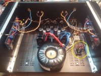
bridge rectifier in place
correct?
the yellow wire under the bridge is conected with a tooth washer and nut. DMM ok for go. the other yellow goes to main ground in the psu pcb
my toroid has an earth wire. i supose that i have to connect it directly to the mains earth. right?
An externally hosted image should be here but it was not working when we last tested it.
correct?
the yellow wire under the bridge is conected with a tooth washer and nut. DMM ok for go. the other yellow goes to main ground in the psu pcb
my toroid has an earth wire. i supose that i have to connect it directly to the mains earth. right?
bridge rectifier in place
An externally hosted image should be here but it was not working when we last tested it.
correct?
the yellow wire under the bridge is conected with a tooth washer and nut. DMM ok for go. the other yellow goes to main ground in the psu pcb
my toroid has an earth wire. i supose that i have to connect it directly to the mains earth. right?
added a 10ohm resistor like the picture above from bk856er
the noise is the same. 0.4mvac. ARTA shows equal results. do you think its time to give up on the ixys?
Last edited:
update:
i have to say something relative to my 3 DMM and a new one that arrived today. it's a low cost DMM UNI-T 139c (true rms). the voltage measured with uni-t is now 0.2-0.3 mvac. i think this is in order with the graph from arta. i wait for your insights because i don't have references in this matter.
my old DMM's are measuring 0.5mvac with this result.
what do you think about the T+N bow?
An externally hosted image should be here but it was not working when we last tested it.
i have to say something relative to my 3 DMM and a new one that arrived today. it's a low cost DMM UNI-T 139c (true rms). the voltage measured with uni-t is now 0.2-0.3 mvac. i think this is in order with the graph from arta. i wait for your insights because i don't have references in this matter.
my old DMM's are measuring 0.5mvac with this result.
what do you think about the T+N bow?
- Home
- Amplifiers
- Pass Labs
- F5 Turbo Builders Thread