Lol
I didn't expect so many replies!!
I like the sound of the F5 turbo over the original. It's more sensible to power an F5 I know as I'm already powering a Jean Hiraga 25w class A in our van.its actually a van converted motorhome with 660w solar panels 4x 155ah batteries 50kg each and Morningstar MPPT controller. It's cosy and me being a musician need a good referance sound!
Abkingsbury. .is the switching that noticeable ? My Hiraga clone has no noise at all! It's a 12v to +-24v PSU. Using an old car amp.
Great your getting your amp going I once built one with the test diyaudio boards a couple of years ago the amp kept blowing despite having success building the F5, ACA and Zen 4 with no problems.
The F5t is the best sounding amp I've ever heard and plan to attempt build two one day. Currently I live in a van though")
6L6 ...
I need to use those batteries in parallel for the electrics lights laptop etc so good idea to wire them in series but no can do
I might as well bite the bullet and buy the original F5 diyaudio boards right? As F5t I's just going to drain those batteries in no time.
Sent from my SM-G900F using Tapatalk
I didn't expect so many replies!!
I like the sound of the F5 turbo over the original. It's more sensible to power an F5 I know as I'm already powering a Jean Hiraga 25w class A in our van.its actually a van converted motorhome with 660w solar panels 4x 155ah batteries 50kg each and Morningstar MPPT controller. It's cosy and me being a musician need a good referance sound!
Abkingsbury. .is the switching that noticeable ? My Hiraga clone has no noise at all! It's a 12v to +-24v PSU. Using an old car amp.
Great your getting your amp going I once built one with the test diyaudio boards a couple of years ago the amp kept blowing despite having success building the F5, ACA and Zen 4 with no problems.
The F5t is the best sounding amp I've ever heard and plan to attempt build two one day. Currently I live in a van though
6L6 ...
I need to use those batteries in parallel for the electrics lights laptop etc so good idea to wire them in series but no can do
I might as well bite the bullet and buy the original F5 diyaudio boards right? As F5t I's just going to drain those batteries in no time.
Sent from my SM-G900F using Tapatalk
Last edited:
I've built a couple of these amps with switching power supplies. With off the shelf laptop adapters, as well as with commercial grade open frame modules. Neither were touted as low noise. I did replace the capacitors on both sides, mainly as precaution since I was running high continuous loads.
In both cases noise floor was below -110dB and flat through the audio spectrum. I could detect nothing in the measured or objective evaluation that would support the belief that linear supplies are vastly superior. You do give up a smidge of bass performance but arguably the lack of 50Hz noise helps the midrange and treble response.
When I'm not on the tablet I will post the RMAA FFT and results.
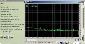
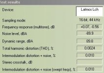
Here's a 4W -> 5ohm FFT and results of a version of the F5 powered from two $25 SMPS units in series, the only change to the supplies was the primary and secondary caps. The supplies are 24V/5A nominal and the adjuster is set for the maximum, or 27.5V.
The output from the SMPS is fed to a mini-CRC bank, the total capacitance is about 35kuF per rail. The bass seems slightly underdamped from when the amp is run off a linear supply. Bias current is about 1.2A per channel.
It sounds really, really good and I have no hesitation in using these kind of supplies for cost-conscious builds.
Attachments
Well I got impatient and decided to have a listen to the first channel and check for ground loop issues before I wired up the second channel.
The sinks are barely even warm with 350mV bias and offset is below a couple of mv. There is zero noise/hum from the speaker with RCAs connected, which I was worried about reading a lot of other problems people had with ground loops. I can put my ear right up to the speaker and it's totally silent
I'm using the amp to drive a homemade two way bookshelf with scanspeak tweeter and 5.5" woofers and the sound is outstanding. This amp just gets it right. Tonal balance and detail are great, the bass is way better than can be expected from a bookshelf. The sound is very effortless even at high volumes. My closest neighbor is about 50 meters from my house and I definitely took advantage of that
I had an F5 previously and in comparison it was a bit dry and lacked the warmth, realism and authority the F5Tv2 has. Can't wait to finish the 2nd channel in the next couple of days and move it onto my big speakers!
Brian
Hi can anybody tell me about P 1 and P 2? Is turning up bias Clockwise or anticlockwise. At 2x 12 v supply( variac) I have 1,7 vdc out ???
Jims Audio PCB Specific thank you.
It depends which way you mounted the pots. It can be measured across some resistors. But don't ask me which ones. Ask Jim.
The pots all the way clockwise ( Zero ohm) and still no bias ? This is a nightmare.
Edit : going to turn it all the way back and maybe change the 1 resistor. Hope not because I have to take all the 33000 uf caps out to do it.
Last edited:
Thanks sangram
If I wanted to make an F5 with option to upgrade to F5T what would be the most easiest solution ? Would it be advisible to build it close to the F5t V1?
Sent from my SM-G900F using Tapatalk
The F5 has current limiting which is optional in the T.
I don't find it a bad idea to keep the limiters.
The other big difference is the feedback resistors. That has arguably a massive role in the way the amps perform. You'll have to work out a way to switch them around to make the uograde work.
I find the V1 with three pairs and compensated feedback works the best personally. I retain the thermistor connection of the F5 as well as the limiters, and I generally skip the diodes totally. That's more than enough for my speakers and compensated feedback network. I'm yet to blow one.
Thanks
From what I noticed at a glance is that to build an F5 and upgrade to F5 turbo V1 there are minimal changes just 6 or so resistors to add and an output pair all point to point wired after F5 PCB. And a few resistors need to be higher wattage.
What's the idea of the limiters ?
Ahh ok I see the feedback resistors ...I once had an amp with a variable resistor in the feedback it was pretty cool !
You said you have 3 pairs on your amp Does this mean you had to up the bias more and have even more heat sinking ?
I'm going to power 8 ohm B&W DM23 speakers very good for low price made in 83
Sent from my SM-G900F using Tapatalk
The limiters reduce the gate drive when the outputs are shorted, they are basically a small safety net against shorted outputs. We have a few instances of people dropping RCA plugs on live amplifier outputs and this is a godsend.
I think there is a post on the forum where a user simply added outputs to the F5 and changed very little otherwise. The question was similar, I don't remember him changing out the feedback resistors, though.
The other two questions, the answer would be 'sort of'. I usually start with a power target in mind (which usually depends on speaker efficiency and impedance), and then work on how many pairs, what feedback/gain structure to use and therefore how many devices (and which - I use a few lateral devices now). That then defines the heatsink and power supply requirements, and subsequently the case design.
So far out of four builds (two in progress and two completed) three use lateral mosfsets, one biased at 1.2A/28V and the other two at 1.7A/36V. The one I built with vertical devices was biased at 1.9A/34V. And a pair of balanced monos on the way are planned for 4A/35V. That should be ready in 2025 - since I've been at it for the last 5 years.
I try for a temp rise of 20-23 degrees, as we have to deal with slightly higher ambient temps than most of the planet. The heatsink size, target bias and target temperature are the three 'corners' of thermal properties of the amp.
My bias changes very weird...
Can someone provide input on the following issue please...
The bias in one of the 2 channels in my F5Tv2 is behaving very weird! when I turn on the amplifier the voltage across the source resistors in that channel starts very high (around 420mV) and then starts decreasing slowly with time and heatsink temperature rise reaching about 300mV after about 20 minutes or so. Likewise, the output DC starts around -100mV when the amp is turned on, and then starts increasing positively towards 0mV in the same 20 minutes. So it seems like that channel is behaving contrary to what is supposed, i.e. the bias should increase with time and temperature rise and not the other way around, correct?
Does anybody know what could be causing this "inverse" behaviour on the bias of this channel??
(My other channel seems to work as it should be, i.e. the bias starts low and increases with time and temperature after the amp is turned on, as well as the output Vdc decreases with time/temperature rise.)
Thanks!
Can someone provide input on the following issue please...
The bias in one of the 2 channels in my F5Tv2 is behaving very weird!
when I turn on the amplifier the voltage across the source resistors in that channel starts very high (around 420mV) and then starts decreasing slowly with time and heatsink temperature rise reaching about 300mV after about 20 minutes or so. Likewise, the output DC starts around -100mV when the amp is turned on, and then starts increasing positively towards 0mV in the same 20 minutes. So it seems like that channel is behaving contrary to what is supposed, i.e. the bias should increase with time and temperature rise and not the other way around, correct?Does anybody know what could be causing this "inverse" behaviour on the bias of this channel??
(My other channel seems to work as it should be, i.e. the bias starts low and increases with time and temperature after the amp is turned on, as well as the output Vdc decreases with time/temperature rise.)
Thanks!
I've had this issue before and it mostly relates to badly matched or unmatched output parts - if they are far enough apart they will engage in tug-of-war on a cold start, till their relative temperatures settle down and reach the bias point you set when the amp was fully warmed up.
Some offset drift is normal even with very close parts, but I try to see that it is below 30mV in either direction.
Some offset drift is normal even with very close parts, but I try to see that it is below 30mV in either direction.
Finished my F5Tv2 build
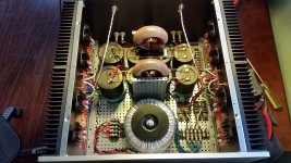
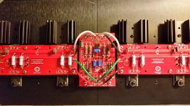
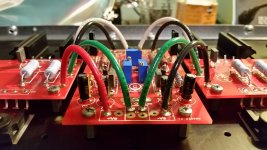
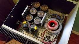
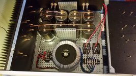
Here's a few pics of my finished build (hoping the attachment worked). Thanks to everyone who contributes on this thread. I read damn near every page of it before starting my build and learned a lot. Without all the help from these forums most of us would never even attempt a build like this!
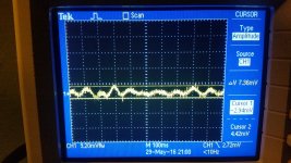
I used the deluxe 5U chasis and boards from the diyaudio store. For the power supply it's a CLC using an Antek 24V 600VA transformer, 6 x 22,000uF Nichicon KG 63V caps and two giant 22,000uF 100V caps (I had them laying around) and Jantzen 7mH iron core torroidal inductors. Rails are 30.7V and the ripple is around 7-8mv so I'm pretty happy. Having the inductors floating on top of the caps was kind of a hack, not really what I was hoping for but just couldn't find another place to put them without getting a custom mounting machined.
Front end Jfets are matched Toshibas cascoded per the F5v3 schematic. Outputs are matched (NNNNPPPP) Toshiba 2SK1530/2SJ201. The amp biased up without any hitch and voltage across source resisotrs on both channels are around 0.340mV with just a couple mV of DC on the output. It was actually barely even warm until I put the lid on the case, which made things heat up at least another 5-10C. I haven't got my thermocouple out but I'm guessing the sinks are around 50C. I used some cool little heatsinks on top of the FETs instead of washers, but inside the case I doubt they're doing much other than distrubiting pressure evenly to keep the FETs coupled to the big sinks.
It sounds great!! I'm driving some custom 6ohm 87db 3 ways with Raal tweeter, Accuton mids and Seas 12" woofer. The amp has no problem making them happy and can drive them far louder than I'll ever listen. I couldn't be any happier with the sound quality.
Now to build up the pile of parts I have for a Buffalo3SE DAC to feed it instead of the soundcard from my PC...
Here's a few pics of my finished build (hoping the attachment worked). Thanks to everyone who contributes on this thread. I read damn near every page of it before starting my build and learned a lot. Without all the help from these forums most of us would never even attempt a build like this!
I used the deluxe 5U chasis and boards from the diyaudio store. For the power supply it's a CLC using an Antek 24V 600VA transformer, 6 x 22,000uF Nichicon KG 63V caps and two giant 22,000uF 100V caps (I had them laying around) and Jantzen 7mH iron core torroidal inductors. Rails are 30.7V and the ripple is around 7-8mv so I'm pretty happy. Having the inductors floating on top of the caps was kind of a hack, not really what I was hoping for but just couldn't find another place to put them without getting a custom mounting machined.
Front end Jfets are matched Toshibas cascoded per the F5v3 schematic. Outputs are matched (NNNNPPPP) Toshiba 2SK1530/2SJ201. The amp biased up without any hitch and voltage across source resisotrs on both channels are around 0.340mV with just a couple mV of DC on the output. It was actually barely even warm until I put the lid on the case, which made things heat up at least another 5-10C. I haven't got my thermocouple out but I'm guessing the sinks are around 50C. I used some cool little heatsinks on top of the FETs instead of washers, but inside the case I doubt they're doing much other than distrubiting pressure evenly to keep the FETs coupled to the big sinks.
It sounds great!! I'm driving some custom 6ohm 87db 3 ways with Raal tweeter, Accuton mids and Seas 12" woofer. The amp has no problem making them happy and can drive them far louder than I'll ever listen. I couldn't be any happier with the sound quality.
Now to build up the pile of parts I have for a Buffalo3SE DAC to feed it instead of the soundcard from my PC...
Attachments
Common Mode DC on input?
I'm about to start building a Buffalo IIISE dac with the Legato v3.1 DC coupled output stage. The Legato has 8-9V of common mode DC, but can be trimmed for 0V DC offset.
So I was wondering can the F5 Turbo v2 can handle the common mode DC of about 8-9V or do I need to AC coupling caps to the output of the DAC? btw, I'm using single ended inputs now but I could switch to balanced if it matters.
Brian
- Home
- Amplifiers
- Pass Labs
- F5 Turbo Builders Thread