I intend to build a F5T with a CLC power supply (using air coils to avoid core saturation).
How much sense does it make to shield the inductors to reduce the magnetic stray field, and to avoid it from interacting with the rest of the electronics?
How would you construct the shielding (material, etc.)?
You have to use coils intended for DC. Hammond are good. I will use 1,5 mh 5 A in mine. Air coils have more stray field then coils with core
You have to use coils intended for DC. Hammond are good. I will use 1,5 mh 5 A in mine. Air coils have more stray field then coils with core
An air inductor will have no problems with DC.
The question is how to shield it (and if it's useful / necessary at all).
Aehm, I believe I am too stupid to make sense of this. Can someone please explain?Nothing to do stupidness
Hi,
I am planningto build a stereo F5Tv2...in a Hifi2000 5U enclosure.
Two question:
1. How high can I go in that enclosure in terms of Watt ?
2. I can get a real decent 2*25V 600VA Transformer...Is one enough ? Or better two with two bridges and two separate PSUs, even if this means internal resistance of the PSU goes up as capacitance is now distributed between both channels ?
For ClassA we generally find recommendations to use a mains transformer rated from 6times to 10times the maximum ClassA output power.
Turning that around, your 600VA transformer should be suitable for a total maximum ClassA output power of 60W to 100W
That would be two channels rated @ 30W+30W to 50W+50W.
An alternative method is to assess the maximum continuous DC current available from the transformer after the capacitor input filter.
A 600VA 25+25Vac transformer has a maximum continuous output of 12Aac
After passing through a capacitor input filter the maximum continuous output is roughly 6Adc depending on the de-rating specified by the manufacturer.
Operating a 600VA 25+25Vac transformer with a continuous 6Adc output will run hot, very hot, if Ta is that inside a ClassA amplifier.
It is sensible to operate @ ~ 50% of the maximum rating for cool running, i.e. set the continuous DC current draw to ~3Adc
3Adc as a bias current through a pair of ClassA push pull (F5t) amplifiers would equate to 3Apk of ClassA into an 8ohm+8ohm loads. That 3Apk is equivalent to 36W into 8ohms for a total maximum ClassA power of 72W, nicely in between the two guide figures using the first 6times to 10times method.
Personally, I would specify a 1kVA with four secondaries, so that the PSU & amplifiers get the benefit of lower regulation from the biggger transformer and get the isolation between channels from the two sets of dual secondaries. It saves money and saves weight and saves space.
1kVA would allow a comfortable 50W+50W into 8ohms+8ohms and could be stretched to around 70W+70W by choosing a Vac to suit.
Last edited:
Lowering both bias and power suply on F5.
Due to a small heatsink I have built a vertion of F5. I use a smaller transformer with 2x15 V AC. To keep the teprature on "the right side" the bias is 0.8 A (0.4 V). My question is; will this changes influence on the measurement and difference from and ordinare F5 ( likeTHD....). Gain resitors are 220 ohm. Intention is to use it together with a sensitiv horn driver.
Eivind S
Attachments
Aehm, I believe I am too stupid to make sense of this. Can someone please explain?
No one is stupid, especially not Diy:ers!
Look here: audiofilterchokes
Andrew, thx a lot...72 w is perfect for the beginning, so I will start with a 650VA with two 25sec, have than separation on bridges and rectifiers per channel, so that I can later easily integrate a second transformer....if the F5t blows away my current el34 UL amp, which I love. My F4 monos will as well get impasse and than we have a new shootout between concepts...dall driven by a maxed out buffalo dac.
I have a quick question, maybe answered before: My speakers have about 6 ohms. They are pretty efficient line-sources. They like quality, like El34 UL amps a lot. So no big damping factor or current delivery for low ohms required. Bass is anyhow done by two big active subwoofers.
Which F5 sounds best ? Normal F5 vs F5t v1 or F5tv2 ? Are the diodes in the v2 audible ? Anyone done this comparison ? i have pcbs for all versions and the 5U enclosure from hifi2000, a 650va 25v transformer and all the transistors for v2 as I planned v2... but if the v1 version sounds better, I guess it would be strong enough except you tell me that v2 has as well a better sound for some reason...
THX
Last edited:
Hi,
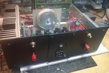
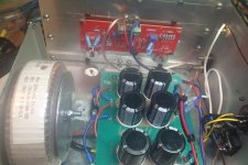
today I want to post the result of my F5T V.2.
Here some details:
Dual Mono Setup: 2 x 800VA toroidals from Toroidy + 2 x 176kuF Elko Capacity from Mundorf
I biased the amp at 2.35A per channel using a pair of 680mOhm source resistors at a voltage drop of ~400mV
Temperature is in the range of 53-55 degree
Offset DC: ~5mV
The housing I'm using is the very large one from Hifi2000.it it is similar to the one you can buy at the diyAudio shop but has a depth of 500mm instead of only 400mm
As you can see I also spent a decent front plate made of plexiglass. I needed to do so because I always want to have a look at the nice toroidals
And here are the pictures:
Hello everybody,
This is my first post in the Pass Labs forum. I’m about to start a F5T V2 build in the next couple of weeks, and trying to study this project, I came to above post from Mallard which shows an excellent build, however I got a bit confused about it in a few aspects, and I’d appreciate if Mallard or someone else could “dissipate” (pun intended) my doubts:
1. The above amp was biased at about 1.18A per output device (4.7A per channel) with the two 0.68 ohm source resistors at a voltage drop of about 0.4V. My first question is, is this value of bias not supposed to make the diodes to conduct immediately? If I’m not mistaken, the diodes start to conduct at about 1 ampere or even a bit less? So I thought the bias should be set at somewhat lower than 1 amp. Am I misunderstanding this?
2. If the voltage rails are +-32V like Mallard mentioned in a following post, isn’t the 4.7A per channel bias a bit high for the total power his amp can dissipate? i.e. is some bias current not kind of "wasted"? (4.7A*4.7A * 8 / 2 = 88.36 W class A) vs. (32V*32V / 8 /2 = 64W)
3. Is there any advantage/disadvantage by going with pairs of 0.68Ohm source resistors instead of pairs of 1 Ohm resistors? Of course, higher bias can be attained with a lower voltage drop at source resistors, but is there a reason papa went with 0.5 Ohm source resistance instead?
I hope these are not dumb questions.

Many thanks in advance.
Last edited:
Sorry, I'm having a bit trouble to understand this. So what is best, the 0.5 ohm source resistance as in the schematic, or lower source resistance (0.34 ohms) as in Mallard's example above?
As I understand it, if 0.5ohms is used, it is recommended a bias of a bit less than an amp (i.e. around 380mV across this source resistance) so that the diodes don't kick in at this idle current, correct? if so, then only 37W class A could be attained (3.04A*3.04A * 8/2 = 36.96W class A at 8ohms). So how can a F5T V2 attain 50W class A (at 8 ohms) using the diodes?
Thank you AudioSan.
Agreed with Audiosan.
This is my first Pass amp as well, so I am just doing the basic build based on the bom from the diyaudio store.
This thread is used to discuss different builds including the standard ones, so we can ask the questions here.
Some people prefer to do modifications to allow more power etc...
And raise the questions here too, like the one that you have brought in so that is the reason for the non-default configuration used over there
This is my first Pass amp as well, so I am just doing the basic build based on the bom from the diyaudio store.
This thread is used to discuss different builds including the standard ones, so we can ask the questions here.
Some people prefer to do modifications to allow more power etc...
And raise the questions here too, like the one that you have brought in
so that is the reason for the non-default configuration used over thereThanks AudioSan and aradan.
But if I set the bias to 0.9A per device per AudioSan's recommendation above, that means a 450mV drop at source resistors (0.5ohms). Then again, is not the recommendation that the voltage drop be no more than 400mV, since just above that value the diodes start conducting? so a voltage drop of 450mV for the bias setting would not be recommended, or yes?
Sorry for not totally understanding this yet. I'm also trying to read as much of the previous posts here as possible. Thank you.
Last edited:
it comes down to temperature of the diodes. you just have to watch the current draw as you adjust it and while you let it settle with the lid on. if the bias current want to run away, yo can drop the diodes all together or you can tweak the source resistance until it don't run away.
- Home
- Amplifiers
- Pass Labs
- F5 Turbo Builders Thread