Thanks roger57, the 100 mOhm resistor oj each rail ( ie CRC ) was already in place. It is now a 50 mOhm.
I'm trying to source some erse 14 awg 4.5 mH coils ( C = 88,000uF/rail/channel ). Erse has 16 awg in stock, and says 500 watt rating. I'm running around 45 VDC at that point, so 500 watt means 11 A capacity. The amp is biased to less than 1/2 of that, so it seems that the 16 awg may just work... 14 awg are not in stock.
Any opinions on the AWG or value of 4.5 mH?
Thanks!
Shouldn't be any issues with respect to current: 16AWG is good for the full 11A.
Did they indicate the DC resistance of the coil?
Can you link me the post that your power supply section is on? (if it is posted?)
If not, can you tell me the arrangement of your caps and resistors of the filter network?
Last edited:
Thanks roger57, the 100 mOhm resistor oj each rail ( ie CRC ) was already in place. It is now a 50 mOhm.
I'm trying to source some erse 14 awg 4.5 mH coils ( C = 88,000uF/rail/channel ). Erse has 16 awg in stock, and says 500 watt rating. I'm running around 45 VDC at that point, so 500 watt means 11 A capacity. The amp is biased to less than 1/2 of that, so it seems that the 16 awg may just work... 14 awg are not in stock.
Any opinions on the AWG or value of 4.5 mH?
Thanks!
With 4.5mH @ 697mOhms, with 6A continuous current, the inductor will dissipate around 19W. Your ripple will be under 5mV peak. That will vary, depending on where your inductor is in the capacitor chain.
Keep some air around that inductor

With 4.5mH @ 697mOhms, with 6A continuous current, the inductor will dissipate around 19W. Your ripple will be under 5mV peak. That will vary, depending on where your inductor is in the capacitor chain.
Also, you will drop about 3.5V across the inductor, so factor that into your calcs!
You'll want to keep some air around that inductor
Thanks roger57, the 100 mOhm resistor oj each rail ( ie CRC ) was already in place. It is now a 50 mOhm.
I'm trying to source some erse 14 awg 4.5 mH coils ( C = 88,000uF/rail/channel ). Erse has 16 awg in stock, and says 500 watt rating. I'm running around 45 VDC at that point, so 500 watt means 11 A capacity. The amp is biased to less than 1/2 of that, so it seems that the 16 awg may just work... 14 awg are not in stock.
Any opinions on the AWG or value of 4.5 mH?
Thanks!
OK, ignore the last posts. 8--) The coil I found wasn't the correct one.
I think this is it:
ERSE - Super Q
At about 6A on the load, it will dissipate around 7W, with a drop of 1.3V across it. Output ripple about 16mV peak. Again, depends on where the coil is in the chain.
The ps is a CLC, with C=44,000uF. Duncan amp tools suggests that with a constant current of 4.3 A, there will be a ripple of 5mv, using this inductor:
ERSE - Super Q
Using a CRC instead, with R=50mOhm => ripple of 20 mV.
ERSE - Super Q
Using a CRC instead, with R=50mOhm => ripple of 20 mV.
The ps is a CLC, with C=44,000uF. Duncan amp tools suggests that with a constant current of 4.3 A, there will be a ripple of 5mv, using this inductor:
ERSE - Super Q
Using a CRC instead, with R=50mOhm => ripple of 20 mV.
Somewhere between 5mV and 10mV is about right for that current. Should sound nice!

The ps is a CLC, with C=44,000uF. Duncan amp tools suggests that with a constant current of 4.3 A, there will be a ripple of 5mv, using this inductor:
ERSE - Super Q
Using a CRC instead, with R=50mOhm => ripple of 20 mV.
Why not measure the ripple with the Oscilloscope first before going ahead with the change?
I was measuring about 6-8mV ripple with my PSU with CRC.


You have the IRFP9240 as well, yes?
The heasinks are nice.
No getting them next, If u remember Im the guy who built an F5 Turbo for a friend when really I shouldn't have (we fell out too lol) which is very unlike me as I usually have no issues with people!
I told him at the time that it was out of my abilities but that I could build him an original F5 as Ive had experience with them. but he insisted I build the bigger and better. and I had so many problems it took up so much of my time, rebuilt the PSU 3 times and it went up in smoke up a couple of times, I quit.
So here I am building my F5 Turbo for myself which I have no pressure or rush to do. Also I can use revision 3 of the Diyaudio boards which will help as I originally was using the first version.
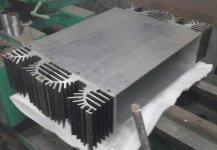
The heat-sinks I like because of the fins, there were others on ebay that had simple fins that were 400mm but I decided to go with the 300mm with cool fins
Im off out to a gig now, catch you laters.
Last edited:
Rix,
They look good.
As I see you have two options on how to use them.
Keep them long and use two face to face to create a tunnel (preferably vertical with fan blowing at the bottom) to be fan driven.
or
Saw them in half and use as passive in a chassis standing 149mm high.
One pair, side by side would be 348wide by 149high by 75thick.
This could be a mono-block,
or use two pairs on opposing sides for a two channel version.
One big mistake with most F5t I have seen on the Forum, is separating the N channel devices from the P channel devices. This is probably down to the way the PCB have been produced.
It would be better to have each P next to an N. This N+P pair can be fed power keeping the loop areas small. Then set up lots of N+P pairs until you reach the dissipation capabilities you require. You could probably put two N+P pairs on one 149mm tall sink.
4 N+P pairs would make a biggish mono F5t, all on one side as described above.
Worth doing a FET + sink dissipation test on the bench.
See how much DC power 4 mosFETs on one 300mm tall sink can dissipate at the temperatures you think you can tolerate. Do this before sawing in half.
Last edited:
Rixsta,
Using the same sinks for my F5 earlier and now the F5 Turbo.
I have them side-by-side for both these (F5 currently in progress, F5T cases are done but rest is yet to be put together). You can see them in some of my posts earlier in this very thread.
A single 10" length can handle about 80W dissipation at 30C delta. Obviously this goes down a bit in summers as the delta becomes smaller, but still over the ~60W requirement of the F5 (per channel).
Two 300mm lengths should manage at least 120-130W dissipation at similar ambient and with good mounting. Over here summers are about 35 degrees so keep that in mind. You may be able to manage to get more power into and out of them.
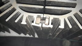
I am using a heatspreader and have not sawed them down, and mine are mounted at the front of the case. The heatspreader is 100mm tallx13" wide, so plenty of thermal footprint. You'll also need the same because those have a raised contact patch. Use M4/5 bolts to hold the spreader down, you'll have to drill the contact patch for that. The little lips on the edge of the extrusion, the outermost fins, can also be used for heatsink alignment using two thin pieces of aluminum and a bolt - a 'lock', so to speak.
magma on this forum has built a similar one, but with three 5" lengths joined by a heatspreader. Not sure how much bias he has been able to put into them.
Using the same sinks for my F5 earlier and now the F5 Turbo.
I have them side-by-side for both these (F5 currently in progress, F5T cases are done but rest is yet to be put together). You can see them in some of my posts earlier in this very thread.
A single 10" length can handle about 80W dissipation at 30C delta. Obviously this goes down a bit in summers as the delta becomes smaller, but still over the ~60W requirement of the F5 (per channel).
Two 300mm lengths should manage at least 120-130W dissipation at similar ambient and with good mounting. Over here summers are about 35 degrees so keep that in mind. You may be able to manage to get more power into and out of them.
I am using a heatspreader and have not sawed them down, and mine are mounted at the front of the case. The heatspreader is 100mm tallx13" wide, so plenty of thermal footprint. You'll also need the same because those have a raised contact patch. Use M4/5 bolts to hold the spreader down, you'll have to drill the contact patch for that. The little lips on the edge of the extrusion, the outermost fins, can also be used for heatsink alignment using two thin pieces of aluminum and a bolt - a 'lock', so to speak.
magma on this forum has built a similar one, but with three 5" lengths joined by a heatspreader. Not sure how much bias he has been able to put into them.
Liliya
Those are on the catalog of many Indian aluminum manufacturers.
I think the original F5 amplifier thread had some discussion when I posted the pictures in 2009. I believe AndrewT had plans to look for similar sinks in European market. We buy ours locally in either small pieces or a single 72" length.
- Home
- Amplifiers
- Pass Labs
- F5 Turbo Builders Thread