So I suppose that P3 changes the relative levels of bias on the P and N channels?
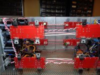
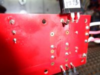
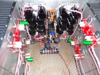
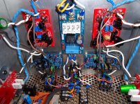
Here are some photos of the damage... do you think the keratherms are still ok? Fire came out of the MOSFETS on the lower board, and blasted the diodes below them.... The first pic shows three Mosfets were breathing fire. I'm pretty sure the fourth one is also toast.
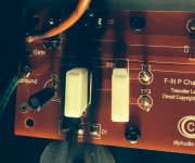
The tool I use to operate P3 is all plastic.
Here are some photos of the damage... do you think the keratherms are still ok? Fire came out of the MOSFETS on the lower board, and blasted the diodes below them.... The first pic shows three Mosfets were breathing fire. I'm pretty sure the fourth one is also toast.
The tool I use to operate P3 is all plastic.
Attachments
Last edited:
So I suppose that P3 changes the relative levels of bias on the P and N channels?
I think that's what P1 and P2 are for. P3 changes the relative feedback or something.
Your amp on fire is quite impressive. I sure am wondering why everything worked so smoothly with mine, considering it's my first amp, I used selfmade boards and I didn't use a light bulb in series nor a variac on my first startup.
My cooling solution, however, is very bad. Have to work around that somehow. Can't close the lid.
Good luck with your new transformer. I should have gotten myself a potted one, too. Mechanical noise is pretty annoying.
") if bias is let to go over the point where the diodes starts cunducting, you have a bias runaway with burned outputs and a fire as a result.
if bias is let to go over the point where the diodes starts cunducting, you have a bias runaway with burned outputs and a fire as a result.Well, there you have it. I will rebias with another set of 4 N-chan transistors and prove that the aux transformer is causing the noise.
I guess the rule is to not twist P3 wildly. If you must play with it, ensure that you are at least monitoring both N and P channel bias levels, and watch that the bias does not exceed 0.4 V on either channel. As I understand it, P3 can introduce an assymetric biasing, which changes the distortion spectrum. If you twist it enough, no doubt, all the bias current can go to one side - in my case the N-channel. P3 can also be used to match the N and P channel bias perfectly, which I believe is the lowest distortion position.
I guess the rule is to not twist P3 wildly. If you must play with it, ensure that you are at least monitoring both N and P channel bias levels, and watch that the bias does not exceed 0.4 V on either channel. As I understand it, P3 can introduce an assymetric biasing, which changes the distortion spectrum. If you twist it enough, no doubt, all the bias current can go to one side - in my case the N-channel. P3 can also be used to match the N and P channel bias perfectly, which I believe is the lowest distortion position.
I forewarned in another Thread that the p3 style of trimmer can set on half of the complementary pair to an effective zero ohms resistance.
I further suggested that a pair of limit resistors be added to the trimmer to avoid what might happen if one source resistor were inadvertently set to zero ohms.
Few seemed to see the necessity for my modification.
I further suggested that a pair of limit resistors be added to the trimmer to avoid what might happen if one source resistor were inadvertently set to zero ohms.
Few seemed to see the necessity for my modification.
After I realized what had happened, I thought that it would be simple to add, say a 50 ohm resistor attached to each side of the trimpot exactly to stop this from happening.
After all, if there is no purpose to trimming the pot entirely to one side or the other, then why allow it?
After all, if there is no purpose to trimming the pot entirely to one side or the other, then why allow it?
Not thinking through what builders could accidentally do !
Your 51r times two and a 500r trimmer gives an effective total resistance of 602r.
The worst setting would be 10r//51r = 8r36 and 10r//551r = 9r82
Maybe 51r is a bit too high, since it restricts the total adjustment.
Maybe 22r, or 33r.
Your 51r times two and a 500r trimmer gives an effective total resistance of 602r.
The worst setting would be 10r//51r = 8r36 and 10r//551r = 9r82
Maybe 51r is a bit too high, since it restricts the total adjustment.
Maybe 22r, or 33r.
BigE, I have only built 5 amps so consider the source...
I'd reconsider the entire build. Not scrap it but reconsider it; great casework but maybe too crowded - maybe go to a twin case power and signal. You might think of getting a minimalist build right first and add to that if you feel it is necessary.
I have lurked for years before I even began building, studying specifically what has gone wrong with anyone's build. Complexity is the enemy. All assumptions should be checked.
Again, consider the source when I say yes, everything on your borads is now suspect. Depopulate and check any and all active devices...and then do it for the passive ones too if you have the patience
Does anyone know if the jfets on the FE board will be affected?
Probably not, but test them...
I'd reconsider the entire build. Not scrap it but reconsider it; great casework but maybe too crowded - maybe go to a twin case power and signal. You might think of getting a minimalist build right first and add to that if you feel it is necessary.
...Complexity is the enemy.
I agree 110%
The big complex thing was the soft-start/slow charge circuit. LTspice helped make that work. The rest ought to be assembly issues -- ie, given that the right parts are installed in the right way, it should "just work". I was listening to it last week, but it was a bit noisy for my liking.
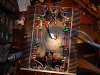
I suspect the aux transformer was putting noise into the circuit.
See photos here
You can see the corner of an open frame transformer at the right hand side of the photo, very near the audio circuit. I've bought a shielded,potted toroid, with the same VA and I hope to see that Friday or Monday.
If *that* does not work, there will be some bigger changes. I really just want to figure out what is wrong with the build. If I can do that, then, I will have learned something. If I abandon this now, and copy someone else's layout, I won't learn as much.
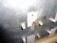
Attached are the photos of the case without the big toroid in it. The safety earth is beneath the IEC, and the ground loop breakers are attached there.
The two terminal strips in front of that allow the selection of secondary voltage.
The front contains the power supply caps, relays, slow charge circuit and rectifiers. One barrier strip is installed to enable the front panel to be removed if necessary.
I suspect the aux transformer was putting noise into the circuit.
See photos here
You can see the corner of an open frame transformer at the right hand side of the photo, very near the audio circuit. I've bought a shielded,potted toroid, with the same VA and I hope to see that Friday or Monday.
If *that* does not work, there will be some bigger changes. I really just want to figure out what is wrong with the build. If I can do that, then, I will have learned something. If I abandon this now, and copy someone else's layout, I won't learn as much.
Attached are the photos of the case without the big toroid in it. The safety earth is beneath the IEC, and the ground loop breakers are attached there.
The two terminal strips in front of that allow the selection of secondary voltage.
The front contains the power supply caps, relays, slow charge circuit and rectifiers. One barrier strip is installed to enable the front panel to be removed if necessary.
Attachments
I do have a question
Is it important that the thermistor and 2.2K resistor on the output board be next to the FE board as drawn on the schematic? If you look at the front panel photo in the preceding post, you will see the thermistor is at the opposite side of the amp from the FE board. I think it should be fine....
Is it important that the thermistor and 2.2K resistor on the output board be next to the FE board as drawn on the schematic? If you look at the front panel photo in the preceding post, you will see the thermistor is at the opposite side of the amp from the FE board. I think it should be fine....
Folks:
One of the F5T V2 amps I built for a friend has found its way back onto my workbench. He reported "nice flames and some smoke" when the amp failed last weekend. I opened it up and found (by visual examination only) that one of the MOSFETs on a P channel output board had failed. The dark marks on the photo are mostly smudges, not shadows.
When I delivered the amp to my friend, the offset on that channel was 1.0 mv after an hour's burn-in, the bias was set at .359 A (P side, .349 on the N side) and the rail voltage was 44.9 VDC. We used a 5U "Deluxe" chassis purchased from the Store. He had the amp sitting out in the open; there was no constricted air flow around it.
I have a matched pair of 12P20 that can be swapped in, but can anyone tell me what might have caused this and what I should test for before installing the replacement MOSFETs? Did I bias the amp too hot or is it likely that this was caused by something else?
Thanks for the input!
Regards,
Scott
Attachments
- Home
- Amplifiers
- Pass Labs
- F5 Turbo Builders Thread