Hi BigE,
With the voltage of the input signals to the amp shielded coax shouldn't be necessary. I found that twist pair works as well with this signal voltage level, your milage may vary.
Routing of the wires though can have a big influence. Keeping small signal wires and PCB traces away from higher voltage ones is important, even if it is supposedly DC.
It sounds like you are working through it methodically.
Good luck,
John
AndrewT, thank you.
I should say, I am referring to 5 Center Tapped secondaries. Anyway, Joffe's test seems to indicate that the transformer is pumping hum onto the ground via parasitic capacitance.
However, in looking at the DCB1, I noticed that I had wired it with the GLB near the circuit, not near the CT. In fact, the CT and power supply common are wired together, and the ground reference for the circuit is taken further away. In my circuit the GLB is at the CT. I the DCB1 it is at the circuit ground. I take it that this would mean that is Main Audio Ground?
Looking at the FE boards, their cluster of grounds, are suggesting that the the FE board be the location of the MAG, and the GLB's should be attached to the FE board, not the CT. In fact, when I rewired the DCB1 and attached the GLB to the CT, there was more noise..... Perhaps, in this manner, the resistance of the ground wire between the DCB1 and F5T is increased? If so, then this is how the F5T ought to be rewired as well -- GBL to FE boards, CT and PS common to FE as well.
johnhenryharris,
When I looked at the photos, it was obvious that I have the FE boards upside down. Flipping them over means the low voltage wiring stays away from the higher voltage stuff. I will certainly do this.
Unitl later gentlemen... right now, I need to replace a fireplace fan blower motor.
Well that was worse. It is SO loud when the DCB1 is plugged in, there is no sense to thing about playing music. Hum is present plugging in one channel at a time. The speaker wire terminators have been changed to avoid the embarrassment of thinking only one channel hums.
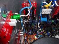
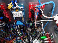
The first photo shows how the CTs are ganged on a shorted barrier strip, as well as the LChan GLB. The second shows the Rchan GLB.
Both barrier strip and the low impedance sides of the GLBs are connected to the chassis and safety earth.
The PSU now has only +'ve, zero volt and -'ve ports. The CTs are disconnected from the cap banks, and are connected only the safety earth.
The DCB1 is wired differently. The audio ground and the CTs are connected.
Can't. Wires are short.
Here are the photos that did not upload. First shows ganged CTs and GLB, second shows Rchan GLB. No more connection of PSU zero volt line and CT. The light brown wire at the FE board that becomes a green wire is the high impedance side connection to the GLB.
On the second photo, you can see the chassis safety earth lug, and all connections to it.
The barrier strips between the IEC and the toroid are the many primaries. You can choose the secondary voltage depending on which primaries you put in series.
Attachments
Last edited:
Can't. Wires are short.
Bummer. I had an amp, an F5T, in fact, that had similar issues to what you describe. Turns out it wall all induced hum from the power transformer.
What I don't get is the measurment of 0 ohms climbing to 13.6 ohms or so (Rchan) between audio ground and safety earth. The Lchan starts at zero and climbs to 12.8 ohms.....
I thought a CL-60 started at a high impedance? Should I change the CL-60 to a 10 ohm resistor?
I will resume banging my head against this wall on Sunday night. Life is calling.
Thanks to everyone for the help.
I shall rewire the DCB1 to disconnect the audio ground from the CTs. Perhaps there is an interaction????
AndrewT,
I am clearly misunderstanding the Main Audio Ground (MAG) concept. I thought the drawing in 3698 shows that the CT as MAG?
Here is a drawing of how it is actually configured at the moment. The drawing shows that the paralleled secondaries are now split into two parts.
Looking at your drawing, I notice that from the cap bank you have a ground wire going to the N ch another to the Pch and from each of them to the FE board. Respectively for the other channel. To me this is a ground loop on each channel.
Perhaps you should have a third ground wire from the cap bank to the FE board and remove the ground connections between the Pch and FE board and Nch and FE board. Or just remove either one of the ground connections between the FE board and Pch or Nch thereby breaking the loop.
Nash
Disconnect the DCB1
Short the inputs of the amplifier, hot to return.
Measure the output offset and output noise on each channel.
Report back.
Will do that tomorrow night, as I away from the beast right now.
Thanks!
Nashbap, I tried that once, to zero effect.
I misunderstood again!!!
What I intend to do Sunday, is to attach the CTs to the zero volt line of the power supply, and the chassis. But, the audio circuit will take it's ground reference from the high impedance side of a ground loop breaker. The zero volt line will not be directly connected to the audio circuit ground reference.
Prior to that, I will take the requested measurements. Then make the change and measure once more.
I think your new wiring description is still wrong.
Connect the secondaries (three twisted wires, ~,CT,~) to the bridge rectifier. One wire, the CT, is unused. It passes over the bridge rectifier, to maintain the low loop area.
Two wires come out of the bridge rectifier, add them to the CT. They now form a three twisted wires triplet of +ve, CT & -ve.
Take this triplet to the Main capacitor smoothing bank.
The output from the other side of the smoothing bank is still a three twisted wire triplet of +ve, Zero Volts & -ve. Take this to the amplifier PCB.
Note that "before" the smoothing bank the wire is called CT, and "after" the smoothing bank it is called PSU Zero Volts. It's the same wire but on different sides of the smoothing bank.
On the CT side it carries current pulses to charge the capacitors. On the Amplifier side it carries audio signals. DO NOT MIX the charging pulses with the audio, NEVER !!!!!
Choose a location on the Zero Volts line, anywhere convenient from the CT to the amp PCB. Connect this "point" to the nearest Chassis panel. Use a direct wire connection, or a Disconnecting Network.
Be aware that all the panels of the Chassis must be electrically CONNECTED to the protected panel that has the PE to Safety Earth bolt.
Last edited:
AndrewT,
Thanks for the clear description. I think I see the problem with the initial installation.
I mixed the audio ground with the CTs. The zero volt line should have a separate connection to the chassis (possibly with a disconnect network). Otherwised, it was ok before. Darn, I was going to do exactly that until my false understanding took over..... now it takes more work to undo.
What confused me in the initial grounding scheme was the notion of the "star ground", which made me think that the CTs and the zero volt line ought to be connected at the same point.
Thank you *very* much. I will report back on the effect of this change, hopefully later tonight.
Like I said the CT is the same wire as the PSU Zero Volts and is also the same wire as the Speaker Return.
If you connect an ohmmeter to Speaker Return and measure to the transformer Centre Tap, you should get a resistance reading very close to 0r0, maybe at most 0r1.
But that wire carries different currents on it's different sections.
It is important to not share different currents through the same length of wire.
That is why I abhor calling everything "Ground".
The CT to Speaker Return wire is what many will mis-name as "Ground" and there lies the wide open door for confusion to charge in.
Tests with QA400, one channel driven, 1KHz@-10 dBFS
Test 1 : CT's connected to PSU, zero volt line from PSU to FE board via both output boards.
Lchan Rchan
THD -65.1 dB/0.055% -36.5 dB/1.5%
THD + N -22.8 dB/7.23 % cannot calculate
SNR 22.8 dB -4.5dB
Then twisting P3 on the Rchan, the Rchan blew up. I don't know if the transistors survived, but the N channel diodes went up in flames.
in this grounding configuration, the center taps were connected to the PSU zero volt line. The zero volt line came out of the PSU and went to the FE board for each channel via the output boards. The audio circuit grounds for each channel were connected to the chassis near the power cords IEC via ground loop breaker connected to the FE board.
The NTC's on the ground loop breaker are ice cold.
I was just turning P3 when it blew up.
- Home
- Amplifiers
- Pass Labs
- F5 Turbo Builders Thread