I'm building a F5 Turbo v2 using the PSU PCBs from the diyStore (and the F5 Turbo PCBs from there as well). I'm planning on using the one 5U chassis for both channels from the diyStore. I'm aiming for +/-32V rails. The 600VA +/-24V Antek 6224 is out of stock. I believe the the 800VA +/-25V transformer would be an appropriate replacement ( AN-8225 - 800VA 25V Transformer - AnTek Products Corp) but just thought I check before purchasing. Is this one ok to use?
Last edited:
the 800VA +/-25V transformer would be an appropriate replacement
25v will get you up to 35.35v after the rectifiers.
24v will get to 33.94.
It will be fine, but beware of the Toshiba's max voltage, which is known to be conservative.
Looks like the AN-8225 is out as well.
dang it. I must have over looked that. I guess I'll go for the 1000VA one then. What effect does increasing the VA have on the amp? Does it introduce more noise or hum?
You start running into hum problems with very large torroid transformers. For example, weight is an obvious problem and also DC in the AC lines from dimmers cause a mechanical hum in the toroid. In fact, they say 800VA and up can cause this issue. There are simple filters that can remedy this. I have one in a 2000VA Balanced power unit.
Anyway, call them and find out when they'll get more in of the 500 and 600VA. And don't forge to let us know.")
Anyway, call them and find out when they'll get more in of the 500 and 600VA. And don't forge to let us know.
25v will get you up to 35.35v after the rectifiers.
24v will get to 33.94.
It will be fine, but beware of the Toshiba's max voltage, which is known to be conservative.
actualy, you will not get so high voltage out of the antek transformers. at least not With 115V/230V mains. the e voltage is given with 120V/240V mains and at low load. with 120V mains you will get around 32VDC under load from thet 2x25V transformer.
may be a good idea to cascode the J-fets
Last edited:
You start running into hum problems with very large torroid transformers. For example, weight is an obvious problem and also DC in the AC lines from dimmers cause a mechanical hum in the toroid. In fact, they say 800VA and up can cause this issue. There are simple filters that can remedy this. I have one in a 2000VA Balanced power unit.
Anyway, call them and find out when they'll get more in of the 500 and 600VA. And don't forge to let us know.
you can also run into hum problem(mecanical hum) with a smal transformer do to heavy load.
in most cases where the transformer hums, it's do to poor winding quallity.
dang it. I must have over looked that. I guess I'll go for the 1000VA one then. What effect does increasing the VA have on the amp? Does it introduce more noise or hum?
I would say its safer to size up than size down.
If your local power utility has DC coming through the lines then you can always put a DC blocker in line with the transformer (DC would be the cause of the hum). But other than that a larger transformer will probably be less noisy, and give a much more stable V and I.
Hi all.
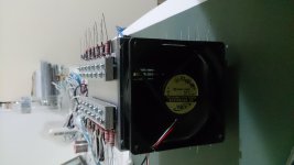
I'm testing how hot I can run my F5.
I went up to 18W/fet (a total of 12 per side) until now. The dissipator was measuring ~42c and the fet drain leg ~53c. I'm concerned because I thought Kerafol would give me a smaller temperature delta. I'm sure the fets are well fixed, besides the fact I'm using clamping bars and washers. Should I worry about this temperature difference?
Many thanks
Daniel
Attachments
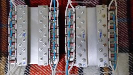
10-11C of difference is good , if they're so crowded
sorry for not being clearer - what I meant - it's hard to achieve perfect pressure on all of them , when so crowded
even counting on kerafol thickness , that demands both surfaces perfectly flat ......
It's a bit high for Kerafol, but we don't know which Kerafol is used.
My experience is that with more pressure you can get a delta of 6 to 8 degrees...
It looks like grey Kerafol, probably softtherm 86/600. Datasheet for the .5mm pads says .2 C/W.
I'm also about to have my crowded F5 turbo ready! Really getting nervous
By the way - making a surface completely flat by hand is terrible work.
Scott,
If you look at pics of the older version and the latest you can clearly see the reduction in hole size. In the version I believe you used, you could easily get 16AWG stranded wire in and with some trimming a 14AWG stranded as you have done. If this is incorrect please let me know. What is the version # silkscreened on your boards? In the latest version you can just about get a 18AWG stranded in. That is the problem. Otherwise the boards look good.
Any luck sorting out the "thinness" in sound you complained about?
Nash (Southern NJ)
Totally agree with you on this... the holes for the hookup wires are SMALLER THAN THE HOLES THAT THE MOSFETS FIT INTO! 18 AWG does NOT fit.
Was this intentional? what can I do about it? Drill them out? and solder from the "right side"? I am totally serious about drilling them out. You cannot even buy a wire pin connector that small.
Last edited:
I am having some troubles....
I started the power supply today, with just two caps per board. I am using Tea Bag's power supply boards, and have a light bulb limiter in place. No amplifier circuitry is connected -- there is no load.
The secondaries on my transformer are centertapped, so I wired the boards in reverse -- the inputs are on the side with the +/- and ground connections. The ground is strapped together with the jumper that Tea Bag's boards provide. The center tap is connected to the power supply ground.
The diyaudio soft start board is being used. The 1.4 KVA transformer starts up perfectly ( it is originally 2.4 KVA, but it is wired to reduce secondary voltage).
I am using a set of 8 relays with 12 VDC coils to control the power supply. They are energized by two 555 timer circuits powered by an independent 9 VDC, 12 VA transformer.
The relays are operated in two steps. 4 of the relays are in one group parallel, they present a 35 ohm load to the timer board. They are Normally Open. These are used to switch power to the diode bridges. There are two diode bridges, one per channel.
The other 4 are also in parallel used to bypass the thermistors. They are changeover relays, with the thermistors connected to the normally closed contacts. One coil operates two relays.
Each relay has an IN914 diode across the coil, with the marking band connected to the +'ve output of the timer circuit.
When the bridges are not connected, the first 4 relays click in unison, and the timer circuit voltage outputs are at 9.3 VDC. Must operate is 9 VDC.
When the first four relays are connected the light bulb flickers as the relays click in and out, then the relays stop clicking and the lightbulb stays dark.
The rail voltages are OK, but the coil voltages drop to below 9 VDC -- about 8.8 VDC.
During this clicking, the light bulb is flashing. The mains voltage sags to about 60 VAC , and then rises back up to 114.3 VAC at which point, the relays stop clicking and the lightbulb stays off.
When the transformer is first powered on and no diode bridges/caps are connected, the voltage is a solid 122 VAC.
The timer circuit does not use a voltage regulator. It does use one 2200 uF cap and a TIP32C transistor per timer to drive the relay coils.
I don't know where to look.
I'm guessing that a 12VAC transformer would be better to power the timer circuit, but then it would need a 12V regulator as the unloaded voltage would exceed the max Vcc of the 555 timer.
Why shoud the mains drop so much and worse, stay low? There is no load here! If they are going to drop to 66 VAC with such little capacitance, there is no way that the relays will stay closed when the rest of the board is filled in.
Mains: 122.2 -> 114.3
Secondary: 33.8 -> 31.7
Rails: 0 -> 42.3
Capacitance: 22,000 uF on positive rail and 22,000 uF on negative rail per channel. There is a 2.2K bleeder resistor involved.
Diode bridges: mur3020, no snubbers.
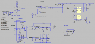
In the attached drawing, only C7 C4 and C2 C9 are present.
Any help would be greatly appreciated!
I started the power supply today, with just two caps per board. I am using Tea Bag's power supply boards, and have a light bulb limiter in place. No amplifier circuitry is connected -- there is no load.
The secondaries on my transformer are centertapped, so I wired the boards in reverse -- the inputs are on the side with the +/- and ground connections. The ground is strapped together with the jumper that Tea Bag's boards provide. The center tap is connected to the power supply ground.
The diyaudio soft start board is being used. The 1.4 KVA transformer starts up perfectly ( it is originally 2.4 KVA, but it is wired to reduce secondary voltage).
I am using a set of 8 relays with 12 VDC coils to control the power supply. They are energized by two 555 timer circuits powered by an independent 9 VDC, 12 VA transformer.
The relays are operated in two steps. 4 of the relays are in one group parallel, they present a 35 ohm load to the timer board. They are Normally Open. These are used to switch power to the diode bridges. There are two diode bridges, one per channel.
The other 4 are also in parallel used to bypass the thermistors. They are changeover relays, with the thermistors connected to the normally closed contacts. One coil operates two relays.
Each relay has an IN914 diode across the coil, with the marking band connected to the +'ve output of the timer circuit.
When the bridges are not connected, the first 4 relays click in unison, and the timer circuit voltage outputs are at 9.3 VDC. Must operate is 9 VDC.
When the first four relays are connected the light bulb flickers as the relays click in and out, then the relays stop clicking and the lightbulb stays dark.
The rail voltages are OK, but the coil voltages drop to below 9 VDC -- about 8.8 VDC.
During this clicking, the light bulb is flashing. The mains voltage sags to about 60 VAC , and then rises back up to 114.3 VAC at which point, the relays stop clicking and the lightbulb stays off.
When the transformer is first powered on and no diode bridges/caps are connected, the voltage is a solid 122 VAC.
The timer circuit does not use a voltage regulator. It does use one 2200 uF cap and a TIP32C transistor per timer to drive the relay coils.
I don't know where to look.
I'm guessing that a 12VAC transformer would be better to power the timer circuit, but then it would need a 12V regulator as the unloaded voltage would exceed the max Vcc of the 555 timer.
Why shoud the mains drop so much and worse, stay low? There is no load here! If they are going to drop to 66 VAC with such little capacitance, there is no way that the relays will stay closed when the rest of the board is filled in.
Mains: 122.2 -> 114.3
Secondary: 33.8 -> 31.7
Rails: 0 -> 42.3
Capacitance: 22,000 uF on positive rail and 22,000 uF on negative rail per channel. There is a 2.2K bleeder resistor involved.
Diode bridges: mur3020, no snubbers.
In the attached drawing, only C7 C4 and C2 C9 are present.
Any help would be greatly appreciated!
Attachments
Nope. Spoke too soon.
For some odd reason, with 4 caps per diode bridge ( 8 total ) the wall voltage goes to 114 VAC. It drops 3 VAC with each cap bank installed.
Is it possible that the caps were damaged? I mistakenly hit them with the voltage of the wrong polarity, but just for a minute or so. This drop in voltage leaves the relay controller outputting 8.8 and 8.9 VDC.... too low.
How is it possible for the wall voltage to drop 6-8 volts with no load?
- Home
- Amplifiers
- Pass Labs
- F5 Turbo Builders Thread