So 1/3 of 32 volts is 10.6v at the voltage divider to the base of the BJT. With the stock resistors 10k and 4.75k in series you have 32 volts across them which gives your 2 ma of current, 32/14.75k. If you want to keep the same voltage to the base and 2 ma current with 48v you need 19.2k for r26 and r25, 48v/(19.2k+4.75K)= 2MA. Sizing R5 and R6 is not as obvious, at least to me, from rail voltage to ground at the source resistors, either R3 or R4, you have 1k + 10ohms so you have 32v/1010ohm = 31 ma if the cascode bjt were bias wide open, which it isn't, but using that for calculations 48v/31ma=1548kohms or about 1.5k. Now this is just educated guess work, which is why I am asking. Another way to look at it is the 48 volt is 50% greater than 32 volts so the resistor R5 and R6 need to be 50% larger, hence 1k to 1.5k.
Analysis/comments please.
Thanks,
John
Analysis/comments please.
Thanks,
John
So, after all that headbashing trying to figure out what why the voltages at the Jfets were so low, it really is the 470K resistor (R29/30) that was mistakenly put in... now exchanged for a 470ohm resisistor and voila! 
Just connected the rest of the circuit, and biased at 0.3V with 1mV offset
Next issue..... now the transformer buzzes/hums .
.
I have 2 hexfreds in the monoblock
http://www.partsconnexion.com/PDF/l363.pdf
I've read somewhere that its possible with something this large and heavy draw it could cause the transformer to buzz?
Its a 1.5kVA toriod with a DC blocker in line.
It was completely silent when I had all the caps in and testing the FE board. But now that there is around 2-3A bias it buzzes.
Any suggestions?
Just connected the rest of the circuit, and biased at 0.3V with 1mV offset
Next issue..... now the transformer buzzes/hums
. I have 2 hexfreds in the monoblock
http://www.partsconnexion.com/PDF/l363.pdf
I've read somewhere that its possible with something this large and heavy draw it could cause the transformer to buzz?
Its a 1.5kVA toriod with a DC blocker in line.
It was completely silent when I had all the caps in and testing the FE board. But now that there is around 2-3A bias it buzzes.
Any suggestions?
So, after all that headbashing trying to figure out what why the voltages at the Jfets were so low, it really is the 470K resistor (R29/30) that was mistakenly put in... now exchanged for a 470ohm resisistor and voila!
Just connected the rest of the circuit, and biased at 0.3V with 1mV offset
Next issue..... now the transformer buzzes/hums
I have 2 hexfreds in the monoblock
http://www.partsconnexion.com/PDF/l363.pdf
I've read somewhere that its possible with something this large and heavy draw it could cause the transformer to buzz?
Its a 1.5kVA toriod with a DC blocker in line.
It was completely silent when I had all the caps in and testing the FE board. But now that there is around 2-3A bias it buzzes.
Any suggestions?
Its actually having to work a little now. If its mechanical hum, try putting a butamen pad under it.
So, after all that headbashing trying to figure out what why the voltages at the Jfets were so low, it really is the 470K resistor (R29/30) that was mistakenly put in... now exchanged for a 470ohm resisistor and voila!
Just connected the rest of the circuit, and biased at 0.3V with 1mV offset
Good to hear that you got this sorted out.
You can help all of us builders if you will share with us some info on your build
Loaded rail voltage?
Are you using Toshiba or IRF Mosfets?
Value of Mosfet source resistors?
Value of R5 and of R11?
What voltage are you getting across R5 with amp fully biased up?
Are P1 and P2 in about the middle position?
Thanks. Nash
Good to hear that you got this sorted out.
You can help all of us builders if you will share with us some info on your build
Loaded rail voltage? 53V
Are you using Toshiba or IRF Mosfets? IRF for now
Value of Mosfet source resistors? 2 x 1ohm in parallel
Value of R5 and of R11? as per schematic
What voltage are you getting across R5 with amp fully biased up? never tested
Are P1 and P2 in about the middle position? Not really sure, I started with them almost at lowest resistance and just turned it up from there. Didn't bother counting the turns.
Thanks. Nash
Only thing is now is trying to figure out why the transformer buzzes so much. at 5-6A total draw it shouldn't be much for a 1.5kVA trafo. Does current imbalance do this ? I'll try swapping the diodes for slower ones tonight and see if it solves the issue.
BTW I didn't put the 1nF cap in... I hope thats not causing issues....
Last edited:
Only thing is now is trying to figure out why the transformer buzzes so much. at 5-6A total draw it shouldn't be much for a 1.5kVA trafo. Does current imbalance do this ? I'll try swapping the diodes for slower ones tonight and see if it solves the issue.
BTW I didn't put the 1nF cap in... I hope thats not causing issues....
If you measure the voltage across the 10r resistor R3 you will know what ma is flowing thru your Jfet. When you get the chance
If you measure the voltage across the 10r resistor R3 you will know what ma is flowing thru your Jfet. When you get the chance
Hmm I don't think its the current draw from the jfet that would cause imbalance. I would put it to the mosfets.
Generally when biased at about 0.295V the other side (N or P) is at 0.290V
Hmm I don't think its the current draw from the jfet that would cause imbalance. I would put it to the mosfets.
Generally when biased at about 0.295V the other side (N or P) is at 0.290V
I only asked for that info as an aid to others. Nothing to do with the hum.
Hmm, matched the bias within 0.002V of each other and still buzzing from the transformer. So I doubt its current imbalance.
I am biased at 0.3V at N and P with about 2-3mV Dc offset. I want to know how much I can take it to until I get thermal runaway.
How can I tell how thermal runaway looks like as far as reading the DMM?
I am biased at 0.3V at N and P with about 2-3mV Dc offset. I want to know how much I can take it to until I get thermal runaway.
How can I tell how thermal runaway looks like as far as reading the DMM?
And your measurements, as you understood them, were substantially correct.So, after all that headbashing trying to figure out what why the voltages at the Jfets were so low, it really is the 470K resistor (R29/30) that was mistakenly put in... now exchanged for a 470ohm resisistor and voila!
Just connected the rest of the circuit, and biased at 0.3V with 1mV offset
......................
You must be unambiguous when addressing a large and varied audience.
Fixing the black probe to ONE location and taking all measurements with "reference" to that one location certainly becomes less ambiguous.
Only when extra resolution of small voltage drops across a high voltage device do you then show Vdrop with + & - correctly allocated.
And yes, my bench DMM is auto range scaling. Very inconvenient, especially since it takes reading very quickly, but finding the correct scale is very slow.
If you have a new pair from Spencer just replace the blown ones with the new pair.
L to R channel Jfet Idss doesn't need to be matched, the bias pots take care of that. What does matter is a good match between the N and P channel Jfet, on that channel's board.
Ok. Jfets replaced and cascode parts added. The channel that was good still works great. The channel that I had to replace the Jfets is now acting wierd. The bias pots seem to only affect one side each. Plus the DC offset does not do anything and just reads 1.2mv.
So I can bring each side up to .3vdc but it's not right.
With music fed in it sounds very distorted and farty.
Print the f5T schemtic and write down the important voltages. Make sure that you have adjustability with both pots without the circuit turned on. It should be roughly zero to sub 1K
Did you lose one polarity of the output transistors in that channel?
Not sure how to know that.
Is there a schematic with voltages on it?
The pots adjust fine with no power.
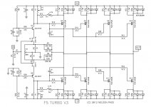
Give me measurements across the following:
r27
r28
r3
r4
r17
r21
R27 and R28 are 18VDC
R3 and R4 are 47ish mVDC
R17 and R21, are these the test points on the Output boards?
These are the resistors that you bias across, correct?
Not sure how to know that.
Is there a schematic with voltages on it?
The pots adjust fine with no power.
Perhaps measuring Idss would tell you if the mosfet was fried or not?
And I am back...
So I re-biased the good channel just to prove I remember how to do it. The other now can only get up to ~6mV before the pots run out or the DC offset is greater then a few mV. Does this mean I need to increase the resistance or that one resistor right? I need to read back on which one. R11 and R12?
So I re-biased the good channel just to prove I remember how to do it. The other now can only get up to ~6mV before the pots run out or the DC offset is greater then a few mV. Does this mean I need to increase the resistance or that one resistor right? I need to read back on which one. R11 and R12?
- Home
- Amplifiers
- Pass Labs
- F5 Turbo Builders Thread