63V rails.
Even with an F5T in class AB, that will not work, unless you run them with "normal" loudspeakers.
With regular sensitivity & impedance loudspeakers, there's no point in going for an F5T.
Allowable rail voltage is determined by the maximum dissipation level.
Max dissipation is not set, just by the output device type and number, also by the heatsink size, and the lowest impedance the amp is supposed to handle without breaking down.
Can anyone suggest a maximum rail voltage for F5 turbo V2, using IRF devices and/or tell me how to calculate this? I have a spare transformer that would give me 63V rails.
The more technically astute DIYer may note that the input Jfets are now
being exposed to greater voltage and dissipation, and this might be a
concern. With respect to voltage, the operating point of these devices is
around 30 volts, 5 volts over their rating. In actual testing these devices
break down around 43 volts, and I depend on Toshiba's famed conservatism
to carry the day. If you don't want to trust Toshiba as much as I do, then you can cascode these devices
Can anyone suggest a maximum rail voltage for F5 turbo V2, using IRF devices and/or tell me how to calculate this? I have a spare transformer that would give me 63V rails.
You could do 63V at 1A bias, provided you have adequate heatsinking(126W). You will definitely need cascode at the input.
3 pairs at output.
Probably not the most ideal operating parameters, but if you already have the transformer it doesn't hurt to build it.
Hopefully your transformer is around 500VA
this is no problem. the boards that will be sold here, you can cascode the J-fets.
but with 63V rails and 2 pair of outputs, the max bias will be around 0.6A pr device(around 40W pr device). so 1.2A bias. thats 20W classA in 8ohms. and a dissipation of 150W pr ch.
Did you finish the test boards yet ...?
Did you finish the test boards yet ...?
hello. no, i'm waiting for the new output boards. but i have been ordering som parts. the plan is to have them up and running before the winter time
")
hi,
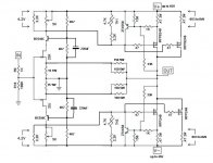
Just got my F5C from the store up and running,I made some mistakes,I lost a output fet,lol.
I used the schematic I've enclosed ,I found alot of variations so This schematic is working good,
I have been reading all the F5 threads,took some time but I'm old school 2n2222,not fets ,lol.But coming up fast,lol.
I have this F5c at 43 vdc,loaded,I have small heatsinks,got fans on them at and biased at .5 there running 95 degrees F,I'll get the screw driver to them in a few days of running,It actually has more power that I need right now,so might bump the bias a little and that's it.
I am using a 5 amp transformer,35A block Bridge,Papa's PS with 6 6800 Nich@63v per side,
I powered a F5 with 2x18 3 amps at 24v with Papa's crc with 8 15,000 Elna,more than enough power,Ready to build a Balanced B-3,I've got the active crossover,almost there!
Happy Listening!
NS
Attachments
hi,
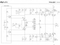
Made some changes to the schematic in post 290, the 220 uf caps changed to 100uf @50,220 was killing the bass, and changed the .47 3w to 2 parrelled 1 R 5 W per fet,and the 150 R 3W changed to 200 ,didn't have any 220 or would have put them here, R7,8,9,10, I also added a 10 uf 50v cap at 2.2K from collector to ground,it helped the DC stability offset it's stable now at .0001ma,I found all this from various schematics posted here,I'm just a follower,Thanks PAPA for all your Ideas you have given me!Sounds good now!Even the wife said what did you do to it ? and hands me a cd,lol.
Feedback or Ideas are always welcome!
Happy Listening!
NS
Last edited:
hi,
Made some changes to the schematic in post 290, the 220 uf caps changed to 100uf @50,220 was killing the bass, and changed the .47 3w to 2 parrelled 1 R 5 W per fet,and the 150 R 3W changed to 200 ,didn't have any 220 or would have put them here, R7,8,9,10, I also added a 10 uf 50v cap at 2.2K from collector to ground,it helped the DC stability offset it's stable now at .0001ma,I found all this from various schematics posted here,I'm just a follower,Thanks PAPA for all your Ideas you have given me!Sounds good now!Even the wife said what did you do to it ? and hands me a cd,lol.
Feedback or Ideas are always welcome!
Happy Listening!
NS
in the original schematic. those 220uF caps are 10uF.
Gee,
I'll redraw the schematic and show what I did ,the reason I changed the parts is I couldn't get it to work right ,I guess I'm dumb too,the schematic posted for that board doesn't match the board,F5c, go look at the store and download the board and schematic and take a look,I was lost,got no responses when I asked about it in the blog , board in the blog is out of date,lol..........so I dove in,lol.It's werkin' good ,sounds good got the F5 sound!!!!!!! so on to the BA 3 the last for aa active 3 way system,,,,
Cheers!
NS
as already verrrrrry well known - I'm dumb
so - there is no surprise that I can't grasp anything about changing 220uF caps , and even more about 10uF going from (which side of ??) 2K2 to gnd ........
i think he ment R5/6. 10uF from R5/R6 to gnd.
EDIT: R5/R6 from the original turbo V3 schematic.
Last edited:
could some one post the correct F5c schematic,The one in post 290 was one from Nelson for Vladamir,I figured if nelson drew it it worked,lol. ,I have seen several all with different values ,and I like to know if you built it it is biased correctly and the values are relitively close ,when I first started P side was .04 ma off from the N side,I did change sk170 to a lower value and it now runs almost the same, and the DC offset is stable with no load at .0001ma,sinks happy at 45 C, I don't profess to be real smart with this as FET's are a new "thing" I was old school but FETS do sound better to me,Just my 2 cents,ok?
NS
NS
Hi audioSan,
Thanks for the schematic,your right that's the one posted ,doesn't it show 2 .47R 3w per fet? and where does the r 105 and 108 go on the board?It show's 4 thermistors connected ,Thanks for your help !!!!!!!
I have 4r7 R101/104 it = 20 volts with 42+ - per rail,If I want more bias I need to increase the resistance on R104 and R 102 and should I change the value for value for P1 and P2 maybe 10K for both pots and R 104,R102? I have changed the source Resistors to 2 1R 5 W Per Fet in parrell to handle more wattage,
Thanks alot!
NS
- Home
- Amplifiers
- Pass Labs
- F5 Turbo Builders Thread