No need. I used 2A fuses with my stereo v2. your fuse is a slow blow and will probably never blow even at higher bias currents.
Thanks for the input. I thought the fuse would blow as soon as I go above 1A/device.
What does it measure?...
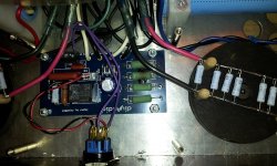
Input shortened, 1h warmup, 2A Bias, DC offset readjusted to <5mV.
DC Offset is dancing from +5mV to -5mV on DMM.
0,1V/Div;5ms/Div

10mV/Div;5ms/Div

Immediatly after PSU switch off
10mV/Div;5ms/Div

Upper trace positive rail to GND
Lower trace negative rail to GND
20mV/Div;5ms/Div

The traces are dancing, thats why you see parallel traces on the last pic.
Thank you for your help!
I have 4A slow blow per monoblock, they will run extra hot")
What's the worst that could happen. You blow a fuse
smoke!
I got a problem tonight with one of the sofstart circuit. I smoked a resistor. I think the culprit is the relay. It did not click when I powered the amplifier so all the power was passing through the resistors bank for all the time it was on until the smoke came out.
The good news is I biased at 1.0A per mosfet and played music on a test rig. Everything is fine. Both monoblock are silent on powering up and powering down. No ground loop either.
I got a problem tonight with one of the sofstart circuit. I smoked a resistor.
I think the culprit is the relay. It did not click when I powered the amplifier so all the power was passing through the resistors bank for all the time it was on until the smoke came out. The good news is I biased at 1.0A per mosfet and played music on a test rig. Everything is fine. Both monoblock are silent on powering up and powering down. No ground loop either.
Attachments
Just a thought... Check the value of C9. The relay will not operate if the value is too low. Specifically, I used 1uF (120v) vice the .33uF (for 220v) for C9. If the relay does not operate you will always have current passing through the parallel resistors and they will get pretty hot. If that were the case you would also never get the full rail voltage your toroidal is capable of so once fixed your bias voltage would be more than previously measured.
Just a thought... Check the value of C9. The relay will not operate if the value is too low. Specifically, I used 1uF (120v) vice the .33uF (for 220v) for C9. If the relay does not operate you will always have current passing through the parallel resistors and they will get pretty hot. If that were the case you would also never get the full rail voltage your toroidal is capable of so once fixed your bias voltage would be more than previously measured.
I'm also using 1uF for C9. I knew the relay was not always working. It never operated with AC line below 120V. It operated when I biased but did not hear it when I tested the amp with music. But thanks, I will check the value of C9 when I will do the repair to be sure.
You need to check the operation of your transformer and any or all control gear BEFORE you connect the PSU.Just a thought... Check the value of C9. The relay will not operate if the value is too low. Specifically, I used 1uF (120v) vice the .33uF (for 220v) for C9. If the relay does not operate you will always have current passing through the parallel resistors and they will get pretty hot. If that were the case you would also never get the full rail voltage your toroidal is capable of so once fixed your bias voltage would be more than previously measured.
Then you need to check the operation of the transformer and control gear and PSU BEFORE you connect a load.
I decided to go from a 2 pair build to a 4 pair build with less bias to see if there was any difference in sound. One channel biased up ok with all the mosfet giving a bias reading within a few mv's of each other.When checking the other channel after warm up one of the p channel devices has a reading across the 0.47R resistor of 150mv's less than the others.
Have I blown it with miss handling?
Advice on what to check please.
Have I blown it with miss handling?
Advice on what to check please.
Pics to follow.It's not biased particularly high.I just wanted to see how a four pair amp would sound compared to a two pair version.Still runs hot though.
Do post your impressions of the sound comparison. I'd be interested in learning. Are you using the diodes in the 2 and 4 versions?
Thanks.
PSU ripple
There was a bad soldering on a bridge diode.
Now the ripple noise on the amp output is more Sinus like, but still about 3.5mVac.
Ripple on rails is 20mVac, and the switching noise of the diodes is still visible on the scope.
According the ZEN-V6 article, push-pull has low PSRR.
Is this also valid for the F5T?
The regulated PSU based on ZEN-V6 article showed only 0.4mVac ripple on LTspice.
Will this hold true on a real world circuit?
Will the regulated PSU also lower the diode switching noise? (I was not able to simulate the diode switching noise)
Has anybode already built an F5V3_T using regulated PSU?
Thanks a lot for any help!
...
>1.0mVac = terrible.
<0.1mVac = very good.
...
I wonder if this points to a particular wiring error?
There was a bad soldering on a bridge diode.
Now the ripple noise on the amp output is more Sinus like, but still about 3.5mVac.
Ripple on rails is 20mVac, and the switching noise of the diodes is still visible on the scope.
According the ZEN-V6 article, push-pull has low PSRR.
Is this also valid for the F5T?
The regulated PSU based on ZEN-V6 article showed only 0.4mVac ripple on LTspice.
Will this hold true on a real world circuit?
Will the regulated PSU also lower the diode switching noise? (I was not able to simulate the diode switching noise)
Has anybode already built an F5V3_T using regulated PSU?
Thanks a lot for any help!
it still looks like you have a wiring errorThere was a bad soldering on a bridge diode.
Now the ripple noise on the amp output is more Sinus like, but still about 3.5mVac.
Ripple on rails is 20mVac,
looks like you need to add a snubber (R+C) across the bridge rectifier.and the switching noise of the diodes is still visible on the scope.
I think it would be a waste of time and resources to build and fit a voltage regulator to the output stage of a big ClassA amplifier............
Has anybode already built an F5V3_T using regulated PSU?.......!
I hope no one has tried.
so new...
I apologize for asking but the stupid questions are the ones unasked right?
I have been through most of this year's posting on this 200+ page thread and done a search; due diligence I hope.
It looks to me that when you purchase a set of boards from the DIYaudio store you don't use two of the gain stage boards when you build F5t v3 monoblocks in stock voltages (35V+/- rails)?
I am unsure of the big picture. Has anyone put one together to describe how all the boards are put to use/linked?
Correct, for V3 you buy two sets of boards and do not use the second set's gain stages.
The output boards have connections on both ends for connecting to the gain stage and linking the boards. A suggestion for layout in a 5U case would be gain stage on the front panel, N- channel boards on one side, the P channels on the other.
You could use the extra gain stage to make it an X Cascoded V2...
- Home
- Amplifiers
- Pass Labs
- F5 Turbo Builders Thread