Hi Mallard,
Very nice build... Impressive the 2 toroids! Are so beautiful that it will be a shame to close them in the enclosure.
Keep us update... with more pictures
Ciao
Enrico
Enrico, yes I know I have to find a way to make them visible somehow

YES - my F5T PSU is up and rinnung correctly - hopefully!
Each channel is showing stable 32.9V without the light bulb.
Now the F5T journey can move on...
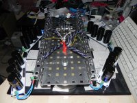
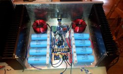
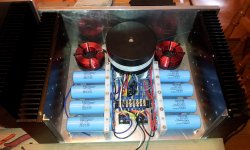
What you can see on the picture is the test setup completely upside down in order to check the correct soldering and wiring.
Each channel is showing stable 32.9V without the light bulb.
Now the F5T journey can move on...
What you can see on the picture is the test setup completely upside down in order to check the correct soldering and wiring.
Attachments
Another Member poking wires through holes in metal panels.YES - my F5T PSU is up and rinnung correctly - hopefully!
Each channel is showing stable 32.9V without the light bulb.
Now the F5T journey can move on...
What you can see on the picture is the test setup completely upside down in order to check the correct soldering and wiring.
Both wires in a wire pair of Flow and Return, MUST pass through the same hole.
This came up in another Thread just recently.
Andrew,
can you please explain why? ...or give me a link to the thread!?
Thanks,
Mallard
can you please explain why? ...or give me a link to the thread!?
Thanks,
Mallard
Another Member poking wires through holes in metal panels.
Both wires in a wire pair of Flow and Return, MUST pass through the same hole.
This came up in another Thread just recently.
Mallard, when you separate the supply and return wires you create an antenna for hum and noise. Keeping all signal and power pairs tightly coupled means they will pick up hum and noise in a manner that exactly cancels out. My first few builds I didn't pay too much attention to this and usually had a bit of hum. Once I became obsessive about keeping the pairs tightly coupled my amps became dead silent. How about that.
So, when passing wires through the baseplate drill a hole large enough to allow both wires of a pair to pass through and install a grommet to prevent shorting. Not quite as easy as passing the wires through the handy holes in the base plate but you won't have to worry about tracing down the source of hum.
So, when passing wires through the baseplate drill a hole large enough to allow both wires of a pair to pass through and install a grommet to prevent shorting. Not quite as easy as passing the wires through the handy holes in the base plate but you won't have to worry about tracing down the source of hum.
The antenna effect becomes MUCH more prominent when a ferrous body is inserted inside the coil.
Passing the two wires through different holes puts that metal plate inside the coil.
Steel and iron will be particularly bad.
Some manufacturers create a narrow slot in the back plate between single pole terminals, for examples the speaker terminals. This slot is to break the antenna effect that would come with two separated holes.
Bob, Andrew... thanks for your replies, very much appreciated!!!
I got your points!
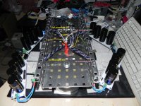
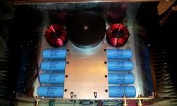
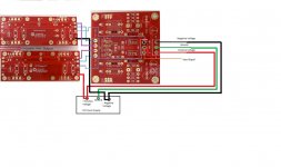
But please see the modified picture! As you can see there are two toroids below the metal case. I have very well drilled each 24V forward and backward wire together.
The only thing is the two 24V ports are seperated for each toroid. This is pretty much how I did my F5 PSU also without any hum. I can't see an issue here because these are
secondary windings and they're separate of each other.
Do you have a recommendation for the shield of each toroid? I'm wondering if I should just put them together and connect with the chassis gnd. (within the metal plate).
I got your points!
But please see the modified picture! As you can see there are two toroids below the metal case. I have very well drilled each 24V forward and backward wire together.
The only thing is the two 24V ports are seperated for each toroid. This is pretty much how I did my F5 PSU also without any hum. I can't see an issue here because these are
secondary windings and they're separate of each other.
Do you have a recommendation for the shield of each toroid? I'm wondering if I should just put them together and connect with the chassis gnd. (within the metal plate).
Attachments
A transformer inter-winding screen should be connected to the enclosing screening Chassis such that the connection forms a VERY LOW impedance route to conduct interference to the screening box.
This demands that the inter-winding screen wire be very short and be connected directly to chassis right beside where it comes out of the transformer.
This demands that the inter-winding screen wire be very short and be connected directly to chassis right beside where it comes out of the transformer.

Pi filter and diode mounting questions
Merry Christmas everybody. My cases for monoblock F5T V2 are finally done and I'm starting the electrical part. This is my first amplifier project and I have 2 questions :
1 - I have 4 air core coils left from a speaker project and I will like to use them in a pi filter in my PSU. They are 1.8 mH 14 Ga (0.3R). Are they big enough to use them instead the usual bank of 0.47R resistors?
2 - Will the diode get to hot if I mount the mosfets on the lower side of the heatsink and the diode on the upper side? I'm afraid that if I mount the mosfets on the upper side, thay will not use the heatsink efficiently enough to cool down.
Thanks
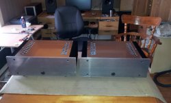
Merry Christmas everybody. My cases for monoblock F5T V2 are finally done and I'm starting the electrical part.
This is my first amplifier project and I have 2 questions : 1 - I have 4 air core coils left from a speaker project and I will like to use them in a pi filter in my PSU. They are 1.8 mH 14 Ga (0.3R). Are they big enough to use them instead the usual bank of 0.47R resistors?
2 - Will the diode get to hot if I mount the mosfets on the lower side of the heatsink and the diode on the upper side? I'm afraid that if I mount the mosfets on the upper side, thay will not use the heatsink efficiently enough to cool down.
Thanks
Last edited:
Pete - Yes, you may try the coils instead of the resistors. You may loose a little rail voltage due to the (comparatively) high resistance of the coils vs. the resistors, but many people report that the coils sound better. Do try it!
Don't worry about the Mosfets or diodes being on the top or bottom of the heatsink. They will be thermally coupled, and I have tried it it both directions, in a 5U store chassis there is no difference in dissipation that I can measure.
Joyeux Noel!
Don't worry about the Mosfets or diodes being on the top or bottom of the heatsink. They will be thermally coupled, and I have tried it it both directions, in a 5U store chassis there is no difference in dissipation that I can measure.
Joyeux Noel!
Thanks a lot Jim! I'm very happy to be able to use these coils and I don't care loosing a bit of rail voltage. This is also a good news about the mounting direction of the diodes.
I will use slow start circuits from the store, then do the CL-60 thermistors are still required?
I will use slow start circuits from the store, then do the CL-60 thermistors are still required?
Does anyone have pictures or wiring diagram using the store boards on how to wire up a 4pr O/P board?
Do I wire it up in series or parallel? I take it that R7 , Th1, and C2 and C1 I only need to populate on one board?
Also the where would I take the output to speaker off of?
Do I wire it up in series or parallel? I take it that R7 , Th1, and C2 and C1 I only need to populate on one board?
Also the where would I take the output to speaker off of?
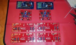
The build is progressing well. I finished the power supply section of left channel today and will do the right channel tomorrow. I won't be able to test those PSU before Monday because I omitted to order one resistor for the soft start boards and I have to wait until they come in...
About the output boards, I soldered the 47.5R gate resistors but I also have 680R resistors on hand just in case. Do everyone had to change those 47.5R resistors for a higher value?
About the output boards, I soldered the 47.5R gate resistors but I also have 680R resistors on hand just in case. Do everyone had to change those 47.5R resistors for a higher value?
Attachments
Does anyone have pictures or wiring diagram using the store boards on how to wire up a 4pr O/P board?
Do I wire it up in series or parallel? I take it that R7 , Th1, and C2 and C1 I only need to populate on one board?
Also the where would I take the output to speaker off of?
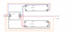
the outputs boards goes in parallel.
here is a diagram for the old prototype boards. conections is the same. just different placement.
Attachments
the outputs boards goes in parallel.
here is a diagram for the old prototype boards. conections is the same. just different placement.
Ok. But what about for the store boards? Just trying to figure out how to plan out wiring scheme for two p and n channels and where to place them in relation to the thermistor and 2k2 resistor.
Ok. But what about for the store boards? Just trying to figure out how to plan out wiring scheme for two p and n channels and where to place them in relation to the thermistor and 2k2 resistor.
I guess that if you have a second pair of output boards, you wire them from one end of the first pair
Attachments
- Home
- Amplifiers
- Pass Labs
- F5 Turbo Builders Thread