If you were to standardise your amp on 63V capacitors, then you will find that a 40+40Vac transformer will run with a fully biased ClassA amplifier at about +-55Vdc.
500mA bias through each pair of output mosFETs will give a device dissipation of ~27W.
Now multiply up the number of output pairs to meet your ClassA target current.
3pair = 3Apk of ClassA
4pr = 4Apk
5pr = 5Apk
etc.
The ClassAB transient current can be much higher
500mA bias through each pair of output mosFETs will give a device dissipation of ~27W.
Now multiply up the number of output pairs to meet your ClassA target current.
3pair = 3Apk of ClassA
4pr = 4Apk
5pr = 5Apk
etc.
The ClassAB transient current can be much higher
...
My specific recommendation to you - use 3 devices and bias until the transistor package is 55C with heatsinks 65C. However, either configuration you make will sound fantastic.")
6L6, don't you mean transistor package at 65C and sink at 55C?
If you were to standardise your amp on 63V capacitors, then you will find that a 40+40Vac transformer will run with a fully biased ClassA amplifier at about +-55Vdc.
500mA bias through each pair of output mosFETs will give a device dissipation of ~27W.
Now multiply up the number of output pairs to meet your ClassA target current.
3pair = 3Apk of ClassA
4pr = 4Apk
5pr = 5Apk
etc.
The ClassAB transient current can be much higher
Thanks Andrew for pointing this out. I realize that for a 100w rms into 8 ohm target with 4pairs of devices, my heat dissipation per device will be much greater with 55V rails then 45V rails given the same bias current; so for 4 pairs it would make more sense to stick with around 45V rails.
Nah, go for broke man !
Run at 55V rails!
Thats what I'm doing, 40-0-40 output trafo, for hopefully 52-55V rails, 63V caps,
lots of heat sinks, 4 case affair!
4 case?? What Class A output are you shooting for? Custom heatsinks? Can't open your images.
Nash
Sorry about the images, I didn't put any in there. I have no idea how they got in there? I can't seem to delete the link either?
Monoblocks with PSU's separate. 4 HeatSink USA 10.080 per channel
1.5kVa trafo's per mono.... just to be sure
going for 1000W room heaters.... I guess I won't be driving the SUV for a while.
Monoblocks with PSU's separate. 4 HeatSink USA 10.080 per channel
1.5kVa trafo's per mono.... just to be sure
going for 1000W room heaters.... I guess I won't be driving the SUV for a while.
Last edited:
The entire point of the cascode version is exactly that - keep the higher voltage from the Jfets, and let the outputs get to the sweetspot with the 32V (or more) rails.
The cascode fets act to keep the higher voltage from burning up the small Jfets - they are kind of an active voltage divider, and add very little sonic flavor to the circuit.
The cascode fets act to keep the higher voltage from burning up the small Jfets - they are kind of an active voltage divider, and add very little sonic flavor to the circuit.
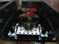
Speaking of F5T cascode - (this is a 2pr v3, or probably better described as a v2 cascode...) Here are some teaser photos. I only have one channel installed in the chassis as of now.
600VA 24+24V with new diyAudio PSU v3 board, (8) 18,000uF caps.
Newest revision PCB, the new front-end will fit on existing holes in the UMS!
Biasing. I have both sets of leads reversed on the red meters, hence the negative values... Lol.
600VA 24+24V with new diyAudio PSU v3 board, (8) 18,000uF caps.
Newest revision PCB, the new front-end will fit on existing holes in the UMS!
Biasing. I have both sets of leads reversed on the red meters, hence the negative values... Lol.
Hi,
Form factor question!
I want to build a pair of monoblocks, using 4 store boards/enclosure and two heatsinks. The intent is to populate the N channel devices on one heat sink and the P channel devices on another heat sink. There will be a total of 4 Mosfets on each sink. Each heat sink is 10" x 10".
Will this fit? I'm thinking yes, since the N channel Mosfets will reside where the empty P channel devices once fit....
Cool!
Once built, I suppose it will be just a matter of setting the bias to a reasonable heat rise.
I wonder how much Class A power I could expect, if the heatsink is 0.8 degC/W/3"?
-------------------
AndrewT suggests that the heatsink capacity goes up with the square root of the size difference. Both AndrewT and Salas suggest that the figure is derated by a factor of near 1.3. I imagine that this factor can be improved by using a copper heat spreader, but never reach 1.0.....
So a 10" sink @ 0.8 deg C/W/3" gives 0.57 deg C/Watt in practice, using the 1.3 derating factor.
Using that number, and a temp rise of 30 degrees, gives, 30/0.57 = 52 watts peak into 8 ohms. 20 degrees gives 35 watts PEAK class A into 8 ohms. (+/- 40 volt rails)
What temps do most of you run your F5T at?
First Results of my F5T V.2 build
After collecting a couple of expensive parts and a few soldering hours I just want to share with you my first results and plans how I want to build my F5T V.2
Of course there is still a lot of work to do: drillings, wiring...
I'm still waiting for all the diodes so I couldn't fire up the PSU for testing.
These big toroidals are so incredibly heavy I have to use a special mounting construction in order to spread the weight smoothly over the biggest possible area.
More to come later on....
Attachments
6L6 looking nice.
Weren't there some issues with the first FE boards wherein some capacitor markings were incorrect? Also I recall reading about your prior build where you had to change the value of one of the resistors (which one ?) and there being a hum issue. Have those been sorted out?
Thanks.
Nash
Weren't there some issues with the first FE boards wherein some capacitor markings were incorrect? Also I recall reading about your prior build where you had to change the value of one of the resistors (which one ?) and there being a hum issue. Have those been sorted out?
Thanks.
Nash
 Very nice build... Impressive the 2 toroids! Are so beautiful that it will be a shame to close them in the enclosure.
Weren't there some issues with the first FE boards wherein some capacitor markings were incorrect?
Not incorrect per se, but the output transistor PCB had it's own numbering.
Also I recall reading about your prior build where you had to change the value of one of the resistors (which one ?)
I increased the gatestoppers (R13 and similar) to 680ohm. This build has (so far) the 47ohm as in the schematic and is stable.
and there being a hum issue. Have those been sorted out?
I haven't had the F5T with both channels attached yet, but I think the hum was a short in an input jack. I had a different amp mounted in the chassis (two, actually) and had no problems since running some tape around the RCA jacks inbetween the washers.
- Home
- Amplifiers
- Pass Labs
- F5 Turbo Builders Thread