
Threads can get tedious. I tend to be a big part of that. Then again, if it was all just facts and figures, it would be boring. You can always start s new thread with any questions you have. Welcome.
Theres alot of truth to that post, but if it wasn't for your help, along with others. We wouldn't get the help needed, we just have to learn or understand what the heck your saying half the time(or maybe thats that Zen fellow who claims his papa is smarter then mine).

Just having fun guys, I enjoy reading your very informative post.
Chassis is almost ready... just waiting for the frontpanel from Andrea in Italy
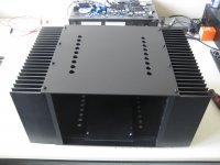
I made a little sub-chassis for the heavy transformers and want to put the rectifying bridges (16 diodes) beneath it. So the 'noisy' BYW99 diodes and ugly 50 Hz cabling are shielded and out of sight.
Do you think the subchassis will hold the dissipation of these diodes ? Or will it become too hot?
A little math: P=UxI, so 0.7 volts x 2,5 Amp per diode = 1.75W x 16= 28 Watts...thats a lot of rectifying heat!
Or is my calculation wrong?
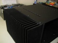
The Teabag amp boards and capacitor boards will be mounted on the heatsinks.
At last I can start with the electronics....although the chassisbuilding was nice also
Should I make the backpanel black too??? I'm in doubt.
Thanks for EUVL whose chassis in the F5X thread was my reference...
I made a little sub-chassis for the heavy transformers and want to put the rectifying bridges (16 diodes) beneath it. So the 'noisy' BYW99 diodes and ugly 50 Hz cabling are shielded and out of sight.
Do you think the subchassis will hold the dissipation of these diodes ? Or will it become too hot?
A little math: P=UxI, so 0.7 volts x 2,5 Amp per diode = 1.75W x 16= 28 Watts...thats a lot of rectifying heat!
Or is my calculation wrong?
The Teabag amp boards and capacitor boards will be mounted on the heatsinks.
At last I can start with the electronics....although the chassisbuilding was nice also
Should I make the backpanel black too??? I'm in doubt.
Thanks for EUVL whose chassis in the F5X thread was my reference...
Attachments
-
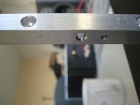 Drilling and tapping.jpg368.5 KB · Views: 348
 -
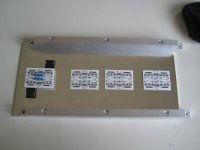 diodes beneath transformer-chassis.jpg231.3 KB · Views: 337
 -
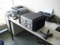
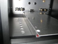 transformer-chassis in case.jpg245.6 KB · Views: 334
 -
 spray-painted.jpg169.5 KB · Views: 325
 -
 chassis-side.jpg253.7 KB · Views: 315
 -
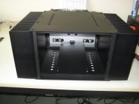 chassis in chassis.jpg264.8 KB · Views: 150
 -
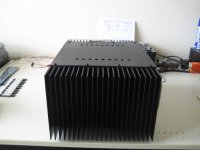 side-sinks.jpg215.9 KB · Views: 140
 -
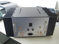 chassis ready back.jpg236.9 KB · Views: 132
 -
 chassis waiting for frontpanel.jpg244.8 KB · Views: 150
 -
 should I make back black too.jpg292.5 KB · Views: 163
Last edited:
aaaargh ...... Dutch Connection 
lookielookie : http://pdf1.alldatasheet.com/datash...UORlHDyRHOIpa/1XXyxeoPonPRrLKl+/datasheet.pdf
rest of questions ?
lookielookie : http://pdf1.alldatasheet.com/datash...UORlHDyRHOIpa/1XXyxeoPonPRrLKl+/datasheet.pdf
rest of questions ?
Teabag F5T convertible boards, stereo dual mono setup. With two 2sj201 and two 2sk1530 per channel which i want to bias a bit higher around 1.25A per MOSFET. So with 32 volt around 40 Watt dissipation each.
These MOSFETS are so big and the heatsinks also, so I think they will hold...
total of 160 Watt per heatsink, but if it's getting too hot, I give them around 1 Ampere bias.
Graetzs? ah Google is my best friend... one rectifying bridge a rail (4 diodes/rail) so 16 Graetzs
These MOSFETS are so big and the heatsinks also, so I think they will hold...
total of 160 Watt per heatsink, but if it's getting too hot, I give them around 1 Ampere bias.
Graetzs? ah Google is my best friend... one rectifying bridge a rail (4 diodes/rail) so 16 Graetzs
16 diodes for two channels seems like four power rails each with four diodes. That can only come about by having a bridge rectifier on each of four secondaries............ Or will it become too hot?
A little math: P=UxI, so 0.7 volts x 2,5 Amp per diode = 1.75W x 16= 28 Watts...thats a lot of rectifying heat!
Or is my calculation wrong?..........
Now look at a secondary with a bridge rectifier.
One pair of series rectifiers passes current in one direction. The other pair of rectifiers passes current when the AC phase is reversed. That means the rectifiers operate @ 50% duty cycle.
Apply 50% duty cycle to your 28W for an effective 14W when the diodes are passing 2.5Arms to the smoothing caps.
Q: what is the rms current charging the smoothing capacitors?
If you were to adopt a single bridge on a pair of secondaries you could reduce the heat losses in the remaining eight rectifier diodes to just 7W.
Last edited:

Or is my calculation wrong?
Yep, very.
Short pulses, higher Vf, but much higher dVxdI product per dissipated diode W.
Not 2.5A continuous per diode.
- Status
- This old topic is closed. If you want to reopen this topic, contact a moderator using the "Report Post" button.
- Home
- Amplifiers
- Pass Labs
- F5 Turbo Circuit Boards