Variac (and Audiosan and Teabag):
UKToecutter is gone? That is not good news. Please tell us that diyaudio will make a power supply board available that is suitable for 16 of those gorgeous Nichicon KG (35mm dia) caps that I just bought through Buzzforb's F5T group buy.
Please, please, please!
Regards,
Scott
UKToecutter is gone? That is not good news. Please tell us that diyaudio will make a power supply board available that is suitable for 16 of those gorgeous Nichicon KG (35mm dia) caps that I just bought through Buzzforb's F5T group buy.
Please, please, please!
Regards,
Scott
Guys,
The current plan (for board Buzz mentions) is to use a 4x each rail 35mm diameter caps for a board that is built to be compact as possible, but still use Panasonics 4pin 35mm 22,000 50v caps, or larger ones with less voltage. It is meant to be a generic dual rail power supply, but carry enough capacitance to work with F5T. At the time of development, all of the F5T stuff CRT and myself have been designing was meant to be an alternative to ToeCutters work, for different purposes. Buzz's group buy was to cater to that.
If anyone has a functioning board and the Gerber file for the Toecutter Power supply, I don't mind getting a limited amount of them printed up. But as I understood it ages ago - there were some layout issues with it.
Guys,
The current plan (for board Buzz mentions) is to use a 4x each rail 35mm diameter caps for a board that is built to be compact as possible, but still use Panasonics 4pin 35mm 22,000 50v caps, or larger ones with less voltage.
If you want to build a real powerful amp you need 63V caps. The 4pin 22.000uF Panasonics with 63V are 40mm. 4x40mm cap per rail plus space for MUR3060 diodes on heatsinks would be my wish. Maybe solder lugs to connect a off board power resistor for CRC use.
Guys,
The current plan (for board Buzz mentions) is to use a 4x each rail 35mm diameter caps for a board that is built to be compact as possible, but still use Panasonics 4pin 35mm 22,000 50v caps, or larger ones with less voltage. It is meant to be a generic dual rail power supply, but carry enough capacitance to work with F5T. At the time of development, all of the F5T stuff CRT and myself have been designing was meant to be an alternative to ToeCutters work, for different purposes. Buzz's group buy was to cater to that.
If anyone has a functioning board and the Gerber file for the Toecutter Power supply, I don't mind getting a limited amount of them printed up. But as I understood it ages ago - there were some layout issues with it.
I think Toecutter had worked out the few issues I pointed out. Can you make a gerber out of a pdf?
So he is not part of DIYAUDIO community anymore?
Not that I am an important member/contributor, I have thought about if I die or suddenly become unable to be a part of this community, no one that personally knows me would ever think to let the community know.
I certainly do miss Toecutter and would miss many contributing members if they suddenly stopped posting. I should tell my wife to post a message somewhere if that happened. Wonder where it could be posted?
Rush
Rush, your getting too deep. That said I think we've lost 3 people for sure in my time here.
I have never heard of scanning a PDF to gerber, especially if it's dual sided.
Yes, I was getting too deep. But how would anyone know if you really "lost" someone. The 3 you know of, someone had to tell you about.
I know nothing about gerber files. Seems like with jpg files posted someone could recreate without starting from scratch, but I don't know.
Rush
couple simple solutions. Any board you buy can always be bridged to another to add components. For instance, the chip amp Aleph board can hold 6 big caps and easily be daisy chained for more caps. I have done this personally. The board Tea has showed me will do the same. Main reason a large board has not been done is size. The smallest I have been able to get a board that will hold all 8 35mm caps is 7" x 8". That is big, but when talking about 100W Class A, it goes with territory. I can assure you that a case to house an amp with that kind of dissipation will have the space. I am sure that Tea will do whatever, but i would imagine some sort of commitment is in order. If nothing comes about, I will make a layout available for those who want to etch at home.
Can I use a Metal bridge rectifier instead of MUR3020W
For the F5T V2 build can I use a 50A, 1000 PIV Metal bridge rectifier instead of a bridge made out of MUR 3020W as Papa has suggested. I don't have space on the power supply PCB to accommodate the diodes and hence this question.
Will there be any noise issues on the DC side. The cap bank is 8 X 10000 microfarads per rail.
Thanks.
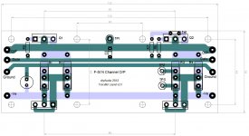
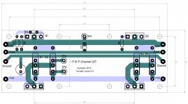
The boards will not be all one board. There will be a gain board with 2 channels, and N output boards and P output boards. Each board has 2 MOSFETS and 2 diodes. For the big diyAudio 5U x 400 deep chassis you can put two of the boards on each side, ie 2 P's on one side and 2 N's on the other side, or one P and one N on each side.
This is quite versatile as you can make mono-blocks or 2 ch amps,
With 2 output devices per side or 4 per side.
And they all bolt onto the drilled tapped holes on the diyAudio chassis heatsinks. the chassis' will be in stock in the next week or 2 .
I explained the modular boards earlier on this thread. Maybe someone can find the posts.
UK Toecutter just disappeared. Maybe he got busy, or bored, or sick of people constantly suggesting changes!
(including me- I started the whole modular board thing, but they needed to fit the new chassis' as there is a lot of interest in using them
for this project). There was some concern that his diodes on the PSU board didn't have adequate heatsinking.
(including me- I started the whole modular board thing, but they needed to fit the new chassis' as there is a lot of interest in using them
for this project). There was some concern that his diodes on the PSU board didn't have adequate heatsinking.
Last edited:
I built up a 5off 15000uF cap bank (+-75mF per channel) for the 100W KSA Klone.The cap bank is 8 X 10000 microfarads per rail.
It put out over 450W into 2r0 and supply ripple was tolerable. See report from a few years back.http://www.diyaudio.com/forums/solid-state/78129-krell-ksa-100mkii-clone-35.html#post1265968
For the F5T V2 build can I use a 50A, 1000 PIV Metal bridge rectifier instead of a bridge made out of MUR 3020W as Papa has suggested. I don't have space on the power supply PCB to accommodate the diodes and hence this question.
Will there be any noise issues on the DC side. The cap bank is 8 X 10000 microfarads per rail.
Thanks.
that will work just fine
")
For the F5T V2 build can I use a 50A, 1000 PIV Metal bridge rectifier instead of a bridge made out of MUR 3020W as Papa has suggested. I don't have space on the power supply PCB to accommodate the diodes and hence this question.
Will there be any noise issues on the DC side. The cap bank is 8 X 10000 microfarads per rail.
Thanks.
Just remember to heatsink the bridge adequately.
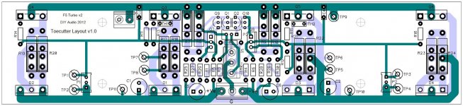
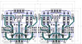
here is the boards gain stage board is breakable so it can be used in monoblock.
for 2 ch you need:
V2: one dual gain stage. 2x P ch outputs. 2x N ch outputs.
V3: one dual gain stage. 4x P ch outputs. 4x N ch outputs.
EDIT: don't mind the marking error
gain stage board is breakable so it can be used in monoblock.for 2 ch you need:
V2: one dual gain stage. 2x P ch outputs. 2x N ch outputs.
V3: one dual gain stage. 4x P ch outputs. 4x N ch outputs.
EDIT: don't mind the marking error
Attachments
Last edited:
- Status
- This old topic is closed. If you want to reopen this topic, contact a moderator using the "Report Post" button.
- Home
- Amplifiers
- Pass Labs
- F5 Turbo Circuit Boards