Even if it were a bass only speaker.
I keep referring to our average listening levels of 10 to 30dB below our maximum power levels, when listening loud.
It appears Members are not appreciating average levels and always assuming that peak levels are continuous. Peak levels cannot be continuous except with DC and we don't listen to DC !
I keep referring to our average listening levels of 10 to 30dB below our maximum power levels, when listening loud.
It appears Members are not appreciating average levels and always assuming that peak levels are continuous. Peak levels cannot be continuous except with DC and we don't listen to DC !
I agree 100%. Psu diodes may present slightly different issue, but as far as source diodes go, I think it is only necessary to couple them to each other vs major heatsinking. In V3, with just 1A through each diode, you can pass, 8A to the load. With 32Vthe rails, that is a lot of power. Considering also that your diodes will only be dissipating 1W each and 8wthe total, and that is figuring safely.
Have we seen advice on what the Vr (=Vf) should be across the diode bypasses/source resistors for normal operation?
The previous Vr of >=500mV does not seem appropriate. That forces the diode to pass an unknown current that is completely unrelated to the stabilising effect of the source resistor.
The previous Vr of >=500mV does not seem appropriate. That forces the diode to pass an unknown current that is completely unrelated to the stabilising effect of the source resistor.
I note that the F5 Turbo V3 uses unobtainable FQA19N20 MOS-FETs.
Now I can get FQAxxNxx devices that have a higher Ciss, Cgs and Cout --
OR FQP19N20 devices that are electrically identical but have almost double Th(js) due to their TO220 packaging.
Does anyone have any views as to which would be the better way to go?
I would guess that the FQP19N20 would be better but more attention would have to be taken to cooling.
I note that the F5 Turbo V3 uses unobtainable FQA19N20 MOS-FETs.
Now I can get FQAxxNxx devices that have a higher Ciss, Cgs and Cout --
OR FQP19N20 devices that are electrically identical but have almost double Th(js) due to their TO220 packaging.
Does anyone have any views as to which would be the better way to go?
I would guess that the FQP19N20 would be better but more attention would have to be taken to cooling.
My solution to that - build a board that will do both...
TO-220 front, backTO-3P/247 packages.
Also using Vishay U30DCT diodes in smaller package as an option.
I think bias levels may have to suffer, but with adequate sinking and attachment to sink, its possible. The actual part inside the packages are very small, so it's about spreading drain heat afiak. Otherwise the FQP's make equal spec part (except dissipation) and are still available, not obsolete etc.
Attachments
Last edited:
Have we seen advice on what the Vr (=Vf) should be across the diode bypasses/source resistors for normal operation?
The previous Vr of >=500mV does not seem appropriate. That forces the diode to pass an unknown current that is completely unrelated to the stabilising effect of the source resistor.
Actually, If the diodes are kept away from the heat of the mosfets, they shold conducting in perfect unison with the Vdrop across the parallel 1R source resistors. If you attach them to the heatsink and and they see the heat generated by the mosfets, they will begin to conduct earlier andit would seem that you lose some of the degeneration and stablilization effect of the source resistors.
I note that the F5 Turbo V3 uses unobtainable FQA19N20 MOS-FETs.
Now I can get FQAxxNxx devices that have a higher Ciss, Cgs and Cout --
OR FQP19N20 devices that are electrically identical but have almost double Th(js) due to their TO220 packaging.
Does anyone have any views as to which would be the better way to go?
I would guess that the FQP19N20 would be better but more attention would have to be taken to cooling.
Look at my signature
") If the susbstitute doesnt suit you, TeaBag is selling the FQP counterparts i believe.
If the susbstitute doesnt suit you, TeaBag is selling the FQP counterparts i believe.
Last edited:
Is there a preference for the V3 and why .....?
Two things jump out. First, it is capable of more power, if needed. Second, the cascoded front end, provides a very stable little nest for the jfets to operate in. Maybe this is important, maybe not. You have to decide.
Ok,
More power ...... Chk !
Cascoded front end ..... Chk !
Is this now simplified as to just pick your F5T Kit ......?
The build continues
Got more done today (hope the boss isn't reading this).
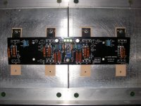
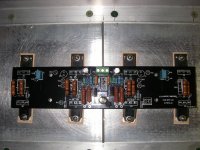
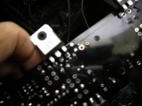
Put all the transistors and diodes on the board and heatsink.
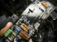
Didn't want to use a terminal block for the speaker output so I had to drill the hole out to except 14 gage wire (5/64" drill), then had to scrape the black paint off so there was something to solder to, front and back, as the drill cut all the tinned copper away.
Second thing, the input ground, again not using a terminal block and I had previously soldered the jumper wire, no place to solder the input ground. I did solder it to the jumper on top, not great, but will do. If I was smart, (and we know I am not) I would have used a longer stripped piece of ground wire and run the end up through the second hole and then soldered it.
Andy I would recommend a third hole for the ground; one hole for the input ground wire and two holes for the jumper, even if you use a terminal block, this is easier than stuffing 2 wires in one hole.
More to come later,
Rush
Got more done today (hope the boss isn't reading this).
Put all the transistors and diodes on the board and heatsink.
Didn't want to use a terminal block for the speaker output so I had to drill the hole out to except 14 gage wire (5/64" drill), then had to scrape the black paint off so there was something to solder to, front and back, as the drill cut all the tinned copper away.
Second thing, the input ground, again not using a terminal block and I had previously soldered the jumper wire, no place to solder the input ground. I did solder it to the jumper on top, not great, but will do. If I was smart, (and we know I am not) I would have used a longer stripped piece of ground wire and run the end up through the second hole and then soldered it.
Andy I would recommend a third hole for the ground; one hole for the input ground wire and two holes for the jumper, even if you use a terminal block, this is easier than stuffing 2 wires in one hole.
More to come later,
Rush
Attachments
Thinking Again
I am getting close to hooking up the power supply and warming this baby up.
I have followed the schematic with all resistor values, except as noted with the cascode resistors. R17-24 are all 1 ohm and I will initially bias them to .3 volt as Mr. Pass noted in the Turbo manual. So when I read .3 volts, with two 1 ohm resistors in parallel (.5 ohm) at each MOSFET, they will only be passing .6 amp each at 32 volt rails, 19 watts. This doesn't seem like anywhere near the sweet spot in the original F5, 22 volts at 1.3 amps, 28 watts. The Turbo doesn't look much like a 50 watt class A amp with such low current.
Am I missing something? Like the current passing in the diode at .3 volts? If so how much is it? I may just be a fraidy-cat, not wanting to smoke these rare Fairchild devises.
Rush
I have had mine at .5 with no problems. Just have to watch the diode temperature. Hotter they get, the faster/earlier they conduct. This was the point of my question about seperating them from the heat. Their response is temperature dependent. Should still be ok, just have to find the point of stability. The Rs are there not only for degeneration and linearization, but also to control the mosfet and temper its response in terms of current consumption.
My tought exactleyI am getting close to hooking up the power supply and warming this baby up.
I have followed the schematic with all resistor values, except as noted with the cascode resistors. R17-24 are all 1 ohm and I will initially bias them to .3 volt as Mr. Pass noted in the Turbo manual. So when I read .3 volts, with two 1 ohm resistors in parallel (.5 ohm) at each MOSFET, they will only be passing .6 amp each at 32 volt rails, 19 watts. This doesn't seem like anywhere near the sweet spot in the original F5, 22 volts at 1.3 amps, 28 watts. The Turbo doesn't look much like a 50 watt class A amp with such low current.
Am I missing something? Like the current passing in the diode at .3 volts? If so how much is it? I may just be a fraidy-cat, not wanting to smoke these rare Fairchild devises.
Rush
what if you reduce the source resistor values? that will let you go up with the bias yes?
I am happy running over 40W on the TO220 FQP19N20s and to me they sound better at hi bias
Just for quick try solder an extra resistor on top of existing one that will give you 0.33 homs and report back
Last edited:
I have had mine at .5 with no problems. Just have to watch the diode temperature. Hotter they get, the faster/earlier they conduct. This was the point of my question about seperating them from the heat. Their response is temperature dependent. Should still be ok, just have to find the point of stability. The Rs are there not only for degeneration and linearization, but also to control the mosfet and temper its response in terms of current consumption.
It is all a game of compromises
If you put them on separate heat sink they will warm up and change curves as you get in the mood to play laud
If you put them on the main heat sink the temperature will be more constant yes they conduct earlier but that can be taken care with changing the value of source resistors
- Status
- This old topic is closed. If you want to reopen this topic, contact a moderator using the "Report Post" button.
- Home
- Amplifiers
- Pass Labs
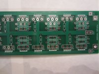
- F5 Turbo Circuit Boards