http://www.diyaudio.com/forums/atta...02d1326899749-my-f5-heat-sink-details-001.jpg
Heath spreaders
why did I not....?
Yeah You wanna Turbo you need intercoolers as well.
While you there and fix heath spreaders there is a bit of it that I like but may not be that plain to see.
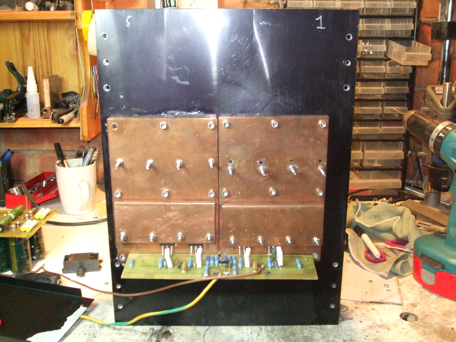
Instead of using silly M3 (sorry for metric) screws with the danger of stripping the treads why not use captive bolts with the heads buried in the spreader
then clamp the mosfets with a bar and nut and washers on outside
This way one can use M4 or larger screws put much more pressure on the mosfets than a single screw would.
especialy if one use Kerafoll this give a much reduced heath Impedence
between mosfet body and the rest of the cooling system
If you can afford it get same cooper (or hunt around for scrap)
The radiated heat is lower than Aluminium (as cooper is mirror like) but the Thermal conductivity is mucho larger (twice ?)
Your sink will run much hotter but the mosfet will be cooler.
On soft start
If any one needs it I got momentary switch to operate a single transistor relay that puls inn the main Trafo trough 2 CL60 in series then the CL 60 are bypasedd by another relay operated again by simple one transistor timer.
Yeah you wanna Turbo you need more petroll one CL60 on a 1000VA tafo is not man enough for the job 2 do but get pretty hot
Heath spreaders
why did I not....?
Yeah You wanna Turbo you need intercoolers as well.
While you there and fix heath spreaders there is a bit of it that I like but may not be that plain to see.
Instead of using silly M3 (sorry for metric) screws with the danger of stripping the treads why not use captive bolts with the heads buried in the spreader
then clamp the mosfets with a bar and nut and washers on outside
This way one can use M4 or larger screws put much more pressure on the mosfets than a single screw would.
especialy if one use Kerafoll this give a much reduced heath Impedence
between mosfet body and the rest of the cooling system
If you can afford it get same cooper (or hunt around for scrap)
The radiated heat is lower than Aluminium (as cooper is mirror like) but the Thermal conductivity is mucho larger (twice ?)
Your sink will run much hotter but the mosfet will be cooler.
On soft start
If any one needs it I got momentary switch to operate a single transistor relay that puls inn the main Trafo trough 2 CL60 in series then the CL 60 are bypasedd by another relay operated again by simple one transistor timer.
Yeah you wanna Turbo you need more petroll one CL60 on a 1000VA tafo is not man enough for the job 2 do but get pretty hot
http://www.diyaudio.com/forums/atta...02d1326899749-my-f5-heat-sink-details-001.jpg
Heath spreaders
why did I not....?
Yeah You wanna Turbo you need intercoolers as well.
While you there and fix heath spreaders there is a bit of it that I like but may not be that plain to see.
Instead of using silly M3 (sorry for metric) screws with the danger of stripping the treads why not use captive bolts with the heads buried in the spreader
then clamp the mosfets with a bar and nut and washers on outside
This way one can use M4 or larger screws put much more pressure on the mosfets than a single screw would.
especialy if one use Kerafoll this give a much reduced heath Impedence
between mosfet body and the rest of the cooling system
If you can afford it get same cooper (or hunt around for scrap)
The radiated heat is lower than Aluminium (as cooper is mirror like) but the Thermal conductivity is mucho larger (twice ?)
Your sink will run much hotter but the mosfet will be cooler.
On soft start
If any one needs it I got momentary switch to operate a single transistor relay that puls inn the main Trafo trough 2 CL60 in series then the CL 60 are bypasedd by another relay operated again by simple one transistor timer.
Yeah you wanna Turbo you need more petroll one CL60 on a 1000VA tafo is not man enough for the job 2 do but get pretty hot
i have been thinking of your bar system. but be carefull!!! with M4 and nut, it's easy to tight it to much and crack the transistor case. use RIGTH amont of pressure. not as much as possible.
http://www.diyaudio.com/forums/atta...02d1326899749-my-f5-heat-sink-details-001.jpg
On soft start
If any one needs it I got momentary switch to operate a single transistor relay that puls inn the main Trafo trough 2 CL60 in series then the CL 60 are bypasedd by another relay operated again by simple one transistor timer.
Yeah you wanna Turbo you need more petroll one CL60 on a 1000VA tafo is not man enough for the job 2 do but get pretty hot
I haven't seen a DIY soft-start that does quite what I want it to. Need one with an on-board transformer, that will bypass a couple CL60's and will reset in case of power failure or brownout.
have to say i agree with that
15mm base might be a good one for class A with some depth.(and split sinks)
or some 10mm heatsprader on 10mm base maybe. this is a guess.
I guess the problem with a heat spreader is achieving good thermal coupling with the main heatsink.
How do you guys manage that?
I guess the problem with a heat spreader is achieving good thermal coupling with the main heatsink.
How do you guys manage that?
yes it is. its a little pain
BTW: thats what i sayd in this thread a few weeks ogo.
I guess the problem with a heat spreader is achieving good thermal coupling with the main heatsink.
How do you guys manage that?
I imagine you spread some thermalcote on and bolt it together. I think the idea is that because heat spreads much farther quickly so the the thermal interface between the copper and aluminum is not quite as critical.
Last edited:
I imagine you spread some thermalcote on and bolt it together.
Sure, I get that.
I'm just wondering how good the thermal coupling is.
I guess I'm trying to decide if I can move heat away from the MOSFETs quicker if they're directly on the heatsing rather than attached to a heatspreader which is then attached to the heatsink.
I imagine you spread some thermalcote on and bolt it together. I think the idea is that because heat spreads much farther quickly so the the thermal interface between the copper and aluminum is not quite as critical.
that is the theory.
the hard part is is to get even thermal coppling over the whole surface.
that demands 100% even surface on heatsink and heatspreader. witch is almost inpossible. you need to use hell of a lot of bolts. and a soft heatspreader, like copper
I once thought of mounting the P type and N types devices on separate copper heat spreaders electrically isolated from the aluminum, so you can mount the outputs directly without any insulator reducing the case temperature even more.
what? thats the wrong way
use one heatspreader with isolation. then you dont need to insulate the heatspreder from the heatsink
what? thats the wrong way
use one heatspreader with isolation. then you dont need to insulate the heatspreder from the heatsink
If the idea is to suck the heat away from the devices quicker then mounting them on the copper with no insulator would work better wouldn't it?
If the idea is to suck the heat away from the devices quicker then mounting them on the copper with no insulator would work better wouldn't it?
thats NOT the idè. it is to spread the heat over a wider area
thats NOT the idè. it is to spread the heat over a wider area
I would think the two go together wouldn't they?
I would think the two go together wouldn't they?
not realy. it dosn't matter if you extract the heat fast. if you deliver it in a smal area. thats just what the transistor do anyway. the problem is to get the heat spread over a larger area. so one big heatspreader does that job better, becouse it it even out the heat over a larger area it self. then that spreader need to get the heat away. with thermal compond and soft material, it will have max effect.
thats NOT the idè. it is to spread the heat over a wider area
The idea is to remove heat from the output device. Spreading it over a wide area is the way to do it.
Because the output devices run so hot, it only makes sense that the heat flowing through a small area between the output device and the heatsink is more concentrated than anywhere else. Thus is it would seem that reducing the thermal resistance at that point would be most beneficial.
i have been thinking of your bar system. but be carefull!!! with M4 and nut, it's easy to tight it to much and crack the transistor case. use RIGTH amont of pressure. not as much as possible.
As much as possible is exactley same as whitout craking up case of the mosfets
that is what i meant and the only restraint.
I haven't seen a DIY soft-start that does quite what I want it to. Need one with an on-board transformer, that will bypass a couple CL60's and will reset in case of power failure or brownout.
I have not tested it for Brown out as we do not get many in the UK and none I can think off in my area
But as it works on charged capacitors to keep the base voltagge and latch the relays tweaking a few resistors may let you set it up for that.
Power out definetley work one have to push momentarynormaly open buton to latch relay
Sorry you missed it there is a picture of it on MY F5 tread
it has been working since last August whitout any problems.
In there there is a protection circuit as well with NTE 7100
dc protection, speaker on dellay and speakers off if V rails drop all included.
- Status
- This old topic is closed. If you want to reopen this topic, contact a moderator using the "Report Post" button.
- Home
- Amplifiers
- Pass Labs
- F5 Turbo Circuit Boards