Does anyone have a rough estimate about heatsink size requirement for the V2 combo board? I was looking for a GB for sinks..
The size depends on whether you are willing to use a quiet fan or just use natural convection. With a fan you get 3x-4x smaller heatsink.
i already let Andy know but for the record:
For me please:
2 input stage boards (70x70mm)
8 single fet output boards (35x50mm),
and please try to make the dimensions stick. no more changes pls Thx.
---------------
Now, if you guys would get past sharing your heatsink designs (everybody's different, Ok, so no details pls..):
Is there some interest maybe in discussing getting matched fets? at least P-to-P and N-to-N matched and then P-to-N side will be left to the trimmer?
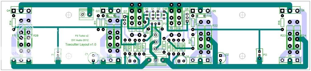
I am not sure why anyone would prefer to use 2 heatsinks with the V2 combo board. The 50 mm MOSFET spacing is too close. That spacing would be optimal spacing for a heatsink that is 100 mm wide.
With the new change, I'm not sure how I'm going to be implementing my design now.
Here's my sink profile:
An externally hosted image should be here but it was not working when we last tested it.
The section is 7" wide and if you look close enough, it is raised in the middle. The older V2 design would be ideal as the devices would be close to the raised center bit, which is also the thickest.
As part of building it I was having it milled fully flat and also using a copper heatspreader, but the devices being close to the bulky bit of the sink would have really helped. I was putting two of these side-by-side, for a 14" wide case.
My F5 used one sink per channel, here it will be two monoblocks with two sinks each, about 12" tall each - four feet of heatsink should be sufficient for a stereo V2.
An externally hosted image should be here but it was not working when we last tested it.
Me sad with the new V2 design

With the new change, I'm not sure how I'm going to be implementing my design now.
Here's my sink profile:
The section is 7" wide and if you look close enough, it is raised in the middle. The older V2 design would be ideal as the devices would be close to the raised center bit, which is also the thickest.
As part of building it I was having it milled fully flat and also using a copper heatspreader, but the devices being close to the bulky bit of the sink would have really helped. I was putting two of these side-by-side, for a 14" wide case.
My F5 used one sink per channel, here it will be two monoblocks with two sinks each, about 12" tall each - four feet of heatsink should be sufficient for a stereo V2.
Me sad with the new V2 design
Very interesting heatsinks. The single MOSFET boards have a pitch of 35 mm and should work with those heatsinks. The main downside is that a separate input stage card must be mounted and wired. It might be prefereable on those heatsinks to mount the MOSFETs vertically rather than side-by-side.
Andy
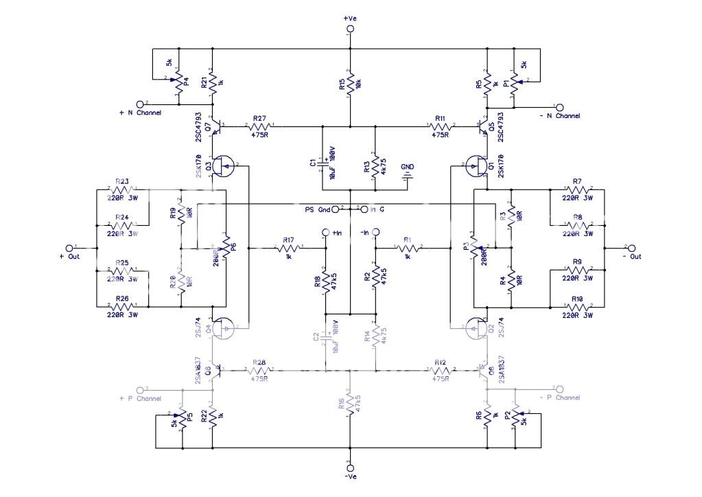
Please can I ask for an extra two holes on the input board. These would be somewhere C5 and R29 (perhaps near the kink in the track) and between C6 and R30. These will help people building the balanced version to enable the cascade devices to share the same reference voltages as per Papa's schematic.
So in the balanced version R25, R27 C5, R26, R28 and C6 will be omitted. Two wires will then join the corresponding points on the two boards.
Andy
Please can I ask for an extra two holes on the input board. These would be somewhere C5 and R29 (perhaps near the kink in the track) and between C6 and R30. These will help people building the balanced version to enable the cascade devices to share the same reference voltages as per Papa's schematic.
So in the balanced version R25, R27 C5, R26, R28 and C6 will be omitted. Two wires will then join the corresponding points on the two boards.
Chalk,
Papa's schematic for the balanced V3 is simplified.
I don't know that you will omit those components. Perhaps somebody else could comment. Papa does say that sharing the same reference voltages is not a requirement.
There is already a provision to connect the two input boards together. A jumper is used across the two positions marked ----link---- if an SE version is being built, if a balanced version is being built the farthest right position connects to the other input board.
When you say holes, I presume you mean pads?
Andy,
Please put me down for:
4x V2 Combo boards
2x PSU boards
Thanks!
Done, on list
Quiet Cooling Fans-
I found this site with a bunch of quiet cooling options and parts. Very interesting.
Quiet Computer Fans
Forced cooling is going to solve the rejected heat problem for lots of people. Might as well start thinking about it now.
I found this site with a bunch of quiet cooling options and parts. Very interesting.
Quiet Computer Fans
Forced cooling is going to solve the rejected heat problem for lots of people. Might as well start thinking about it now.
The F5 Turbo power supply avoids an extra rectifier voltage drop vs the F5 supply. Bob Cordell's book "Designing Audio Power Amplifiers" describes the two rectifier variations, indicating potential problems with the Turbo power supply topology if positive and negative rail currents are different. In that situation, dc current flows through the transformer winding, which is to be avoided.I'm wondering why the F5 Turbo doesn't use two bridge rectifiers like the F5?
Hi Andy,can you count me on F5 turbo V2 ,2 combo boards and 1 PS board.OK
To meet popular demand.
Here's the V2 Combo with mosfets now at 65mm centres and board size reduced to 224mm x 50mm
- Status
- This old topic is closed. If you want to reopen this topic, contact a moderator using the "Report Post" button.
- Home
- Amplifiers
- Pass Labs
- F5 Turbo Circuit Boards