0.325A bias per Motorola, 77Vdc rails, makes 25W.
Six on each heatsink, 36 total, makes 900W dissipation.
The heatsinks Krell used on the 200B are 0.30C/W, so they ran stupidly hot.
Why they broke down so often.
Now back to our regular scheduled program.
+10 Stove hot .....
Actually, i've measured the heatsink model of the KSA200(B), rather admired Krell for it at the time.
The later heatsink model that Krell had made, on e.g. KSA250 and MDA500, was even better. (me been very much into heatsinks since the '80s)
OK Mr heatsinks ....

what was the numbers?
About 10% lower.
The 77Vdc is just a quicky from the memory bank, unloaded rail voltage, so think more like 850W dissipation.
Heatsink temperature was well above 65C in a hot room though, burnt your fingers. One had to dress light to audit a Krell display in those days.
About 10% lower.
The 77Vdc is just a quicky from the memory bank, unloaded rail voltage, so think more like 850W dissipation.
Heatsink temperature was well above 65C in a hot room though, burnt your fingers. One had to dress light to audit a Krell display in those days.
okei. thats about same as my numbers, when you withdraw the 50ish W.
guess ambient vas a little lower den 30C too
at idle
From the wall socket maybe.
Doesn't mean that the heatsinks dissipate 1200 to 1400 watts.
For the record : 0.325A times 18 output devices per channel is 5.85A, divided by 2 makes a quiescent current setting of 2.925A. (the 325mV bias setting number is from the SM)
Is roughly 135 watts full class A (270 peak Class A), the KSA200 did way more than 300W in Class AB.
Most Class A power amps then, and still now, were biased to the peak power level.
Meaning that a power amplifier that was marketed as 100W Class A, was biased to 1.8A, which is 50W continuous and 100W peak Class A.
Everyone did that, saves 30% dissipation.
Now back to F5V, right ?
I will not need more than 50 watt class-a from F5 Turbo .....
Nor will I.
I will probably only populate with two pairs of outputs. The second set of boards will be as spares if I decide to go bigger later.
Glad the mono/stereo debate is over. To each there own, I may mount the heat sinks on the outside wall outside and spray water on them when I want to listen to music. I have a garden right under that so I can grow strawberries in the winter and corn in the summer.
Rush
I've relaid the original board as an F5 V2, so two N & two P Channel Mosfets on the board.
It seems the general consensus is that the V3 needs to have split N & P channel boards for each channel.
Also, The V3 requires one power supply per channel and the V2 can work fine on a single power supply board (stop me if I'm boring you).
SO....
A V3 will require 4 x Output Mosfet boards, 1 x 1st Stage Board and 2 x Power supplies.
A V2 will require 2 x V2 Combination Boards and 1 x Power Supply.
Firstly if someone can check that for me.
Secondy, the cost of a test batch is prohibitivly expensive (then again so is getting the boards wrong).
I could really do with some of you experts to review the boards against the schematics. I really don't want this to go wrong.
Andy


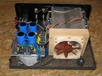
Monoblock: .6 cu ft
This monoblock configuration would work for a 180 watt F5-turbo.
The dimensions are 15"x11.5"x6". It might need to be slightly larger for the bigger toroid transformer. I have actual temperature measurements for 2 x F5 channels at 65W dissipation per channel with only 12C-14C temperature rise.
This monoblock configuration would work for a 180 watt F5-turbo.
The dimensions are 15"x11.5"x6". It might need to be slightly larger for the bigger toroid transformer. I have actual temperature measurements for 2 x F5 channels at 65W dissipation per channel with only 12C-14C temperature rise.
Attachments
I've relaid the original board as an F5 V2, so two N & two P Channel Mosfets on the board.
It seems the general consensus is that the V3 needs to have split N & P channel boards for each channel.
Also, The V3 requires one power supply per channel and the V2 can work fine on a single power supply board (stop me if I'm boring you).
SO....
A V3 will require 4 x Output Mosfet boards, 1 x 1st Stage Board and 2 x Power supplies.
A V2 will require 2 x V2 Combination Boards and 1 x Power Supply.
Firstly if someone can check that for me.
Secondy, the cost of a test batch is prohibitivly expensive (then again so is getting the boards wrong).
I could really do with some of you experts to review the boards against the schematics. I really don't want this to go wrong.
Andy
Andy ,
That's 4 boards /ch for a v3 .....?
So here are the boards
1st Stage V3 board
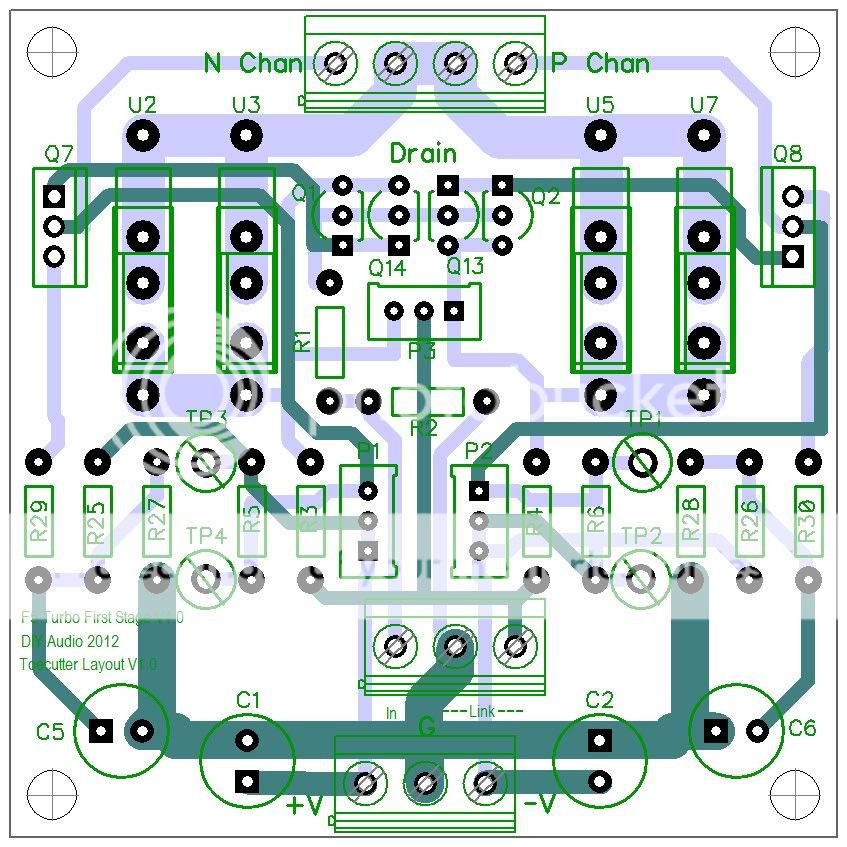
V3 Output Board
An externally hosted image should be here but it was not working when we last tested it.
PSU Board
An externally hosted image should be here but it was not working when we last tested it.
V2 Combo Board
An externally hosted image should be here but it was not working when we last tested it.
Time for bed.....
Sweeeeet .............. V3 lives !!!!!
Last edited:
Boards needed
Wonderful work Andy.
Not necessarily split N & P boards. I would just use 2 of your output boards in parallel.
V3 per channel: 2x Output board, 1x 1st Stage Board, 1 PS board. Preferably in one mono block
V3 stereo: 4x Output board, 2x 1st Stage Board, 2 PS board. Preferably in two mono blocks
V3X per channel: 4x Output board, 2x 1st Stage Board, 1 PS board. Preferably in one mono block
V3X stereo: 8x Output board, 4x 1st Stage Board, 2 PS board. Preferably in two mono blocks
Oh...
V2 stereo 2 x V2 Combination Boards and 1 x PS board. Stereo chassis is ok
For checking the layout and schematics there are better experts here.
Any news from Papa regarding his OK?
I've relaid the original board as an F5 V2, so two N & two P Channel Mosfets on the board.
It seems the general consensus is that the V3 needs to have split N & P channel boards for each channel.
Andy
Wonderful work Andy.
Not necessarily split N & P boards. I would just use 2 of your output boards in parallel.
SO....
A V3 will require 4 x Output Mosfet boards, 1 x 1st Stage Board and 2 x Power supplies.
A V2 will require 2 x V2 Combination Boards and 1 x Power Supply.
Andy
V3 per channel: 2x Output board, 1x 1st Stage Board, 1 PS board. Preferably in one mono block
V3 stereo: 4x Output board, 2x 1st Stage Board, 2 PS board. Preferably in two mono blocks
V3X per channel: 4x Output board, 2x 1st Stage Board, 1 PS board. Preferably in one mono block
V3X stereo: 8x Output board, 4x 1st Stage Board, 2 PS board. Preferably in two mono blocks
Oh...
V2 stereo 2 x V2 Combination Boards and 1 x PS board. Stereo chassis is ok
For checking the layout and schematics there are better experts here.
Any news from Papa regarding his OK?
- Status
- This old topic is closed. If you want to reopen this topic, contact a moderator using the "Report Post" button.
- Home
- Amplifiers
- Pass Labs
- F5 Turbo Circuit Boards