Guys,
The current plan (for board Buzz mentions) is to use a 4x each rail 35mm diameter caps for a board that is built to be compact as possible, but still use Panasonics 4pin 35mm 22,000 50v caps, or larger ones with less voltage. It is meant to be a generic dual rail power supply, but carry enough capacitance to work with F5T. At the time of development, all of the F5T stuff CRT and myself have been designing was meant to be an alternative to ToeCutters work, for different purposes. Buzz's group buy was to cater to that.
If anyone has a functioning board and the Gerber file for the Toecutter Power supply, I don't mind getting a limited amount of them printed up. But as I understood it ages ago - there were some layout issues with it.
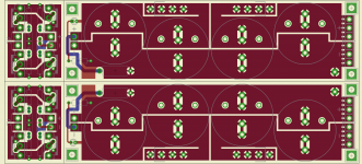
Here is a pic of the current Power supply board we are working on. About 210mm x 90mm
Supports 4x 35mm caps per rail. One 10+ watt resistor for for R in CRC, or you can stack a couple of lower watt ones. MUR diodes meant to chassis mount or heatsink mount with optional snubber mounting for caps and diodes. All should fit little terminal blocks on input and output. Material will be 2.2-3mm think with 2 or 3oz copper. Not meaning to have commercial post - but an option that is out there.
Attachments
The new PSU PCB in the store will have a snap-off part with just the diodes, which can then be folded down to bolt to a surface.Just remember to heatsink the bridge adequately.
On the diyAudio chassis' the front panels are 10mm thick so someone could drill and tap them (need a drill press set so it won't drill through! and a regular tap and a flat bottomed tap) on the back to accept the diodes, and that would be a pretty decent PSU diode heatsink IMHO.
My effort for V2 boards with PS
Hi,
I am trying to make these boards for me. Thanks to FM sachu888 for uploading pics for me.
I designed these board myself and consuming in my build. It would be two mono blocks inside single chassis comprising of 2 X Amps boards, 2 X filter boards and 1 rectifier board.
F5V2 Mono Amp: 292.1 mm X 41.91 mm
Power supply filter: 199.39 mm X 82.55 mm
Power supply rectifier: 209.55 mm X 36.83 mm
Thanks,
Hi,
I am trying to make these boards for me. Thanks to FM sachu888 for uploading pics for me.
I designed these board myself and consuming in my build. It would be two mono blocks inside single chassis comprising of 2 X Amps boards, 2 X filter boards and 1 rectifier board.
F5V2 Mono Amp: 292.1 mm X 41.91 mm
An externally hosted image should be here but it was not working when we last tested it.
Power supply filter: 199.39 mm X 82.55 mm
An externally hosted image should be here but it was not working when we last tested it.
Power supply rectifier: 209.55 mm X 36.83 mm
An externally hosted image should be here but it was not working when we last tested it.
Thanks,
you are better of if you place transistors and diode like this:
from the center of the board. diode, transistor, diode, transistor.
that way you will have more space between the 2 inner transistors. and can get a more even heatsink temp when you are using 2 sinks side be side. when the transistor is placed close to the edge of the sink, you will get a hotspot around the edge.
Here is a pic of the current Power supply board we are working on. About 210mm x 90mm
Supports 4x 35mm caps per rail. One 10+ watt resistor for for R in CRC, or you can stack a couple of lower watt ones. MUR diodes meant to chassis mount or heatsink mount with optional snubber mounting for caps and diodes. All should fit little terminal blocks on input and output. Material will be 2.2-3mm think with 2 or 3oz copper. Not meaning to have commercial post - but an option that is out there.
A lot of people have already paid and received/waiting Buzz's F5T premium kit GB (which was a very good bargain for the quality/price we paid). However the kit included 7 PSU CRC resistors per rail as in NPs' original F5T article, so I'd think most of us would like to see a PSU pcb with those resistor setup in mind. Apart from that, the posted pcb is brilliant, narrow and with 8 total caps positions. My only suggestion is to change the CRC single resistor from parallel position to a 7 resistors scheme (or maybe 4 resistor positions and stack double resistors on 3 slots) between double caps on each side of each rail.
you are better of if you place transistors and diode like this:
from the center of the board. diode, transistor, diode, transistor.
that way you will have more space between the 2 inner transistors. and can get a more even heatsink temp when you are using 2 sinks side be side. when the transistor is placed close to the edge of the sink, you will get a hotspot around the edge.
Thanks,
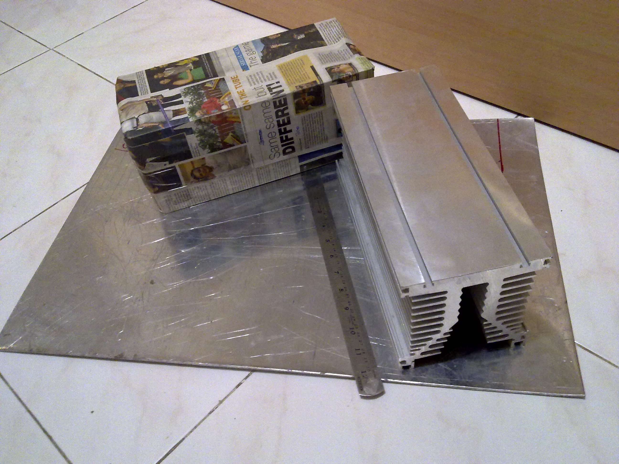
I had this heatsink in mind while designing. I tried to keep equal spacing from edges as well as between MOSFETs.
Its 300mm long, with 16mm base plate
Indeed, one can stack 7 resistors in the proposed PCB and make it work, but to be honest it will look really crappy and odd. And I know TeaBag has a knack for really tidy and cool looking PCBs (his DCB1 was outstanding and also his F5T boards, from what I can see from Buzz's pics and hopefully in his next GB see it from close since I'll probably try both DiyStore and TeaBag boards) which I'm trying to take advantage of! 
Thanks,
I had this heatsink in mind while designing. I tried to keep equal spacing from edges as well as between MOSFETs.
Its 300mm long, with 16mm base plate
so it will be active cooling?(fans)
regarding spacing. that is good thinking
also bare in mind the baseplate thickness(at least with passive cooling) the sinks can efficient spread the heat in a radius of x10 the baseplate thicknessIndeed, one can stack 7 resistors in the proposed PCB and make it work, but to be honest it will look really crappy and odd. And I know TeaBag has a knack for really tidy and cool looking PCBs (his DCB1 was outstanding and also his F5T boards, from what I can see from Buzz's pics and hopefully in his next GB see it from close since I'll probably try both DiyStore and TeaBag boards) which I'm trying to take advantage of!
it realy depends on how one do it
but it can be odd.No there's no need to change a good plan if the majority is satisfied with it. The rest will find a way and follow.
I'm just standing on the fact that these boards are supposed to catter for Buzz's F5T kit GB which already included fourteen .04R/3W Mills resistors @ 28,00 $ (no retail price but GB price). Also some people (not me though) got sixteen Nichicon caps although they can use 2 stacked pcbs, one with CRC resistors, the second one without CRC and diodes' section snapped off.
In any case I'm really glad and grateful for all the effort Teabag and the rest of the F5T diy crew is putting into this project and I'll be happy with any result they come up with.
so it will be active cooling?(fans)
regarding spacing. that is good thinking
First I will be trying without fans, as PCB lengths will be parallel to heatsink length. I will be keeping chassis like vertical tower, (heatsink lengths perpendicular to floor)
Like this -
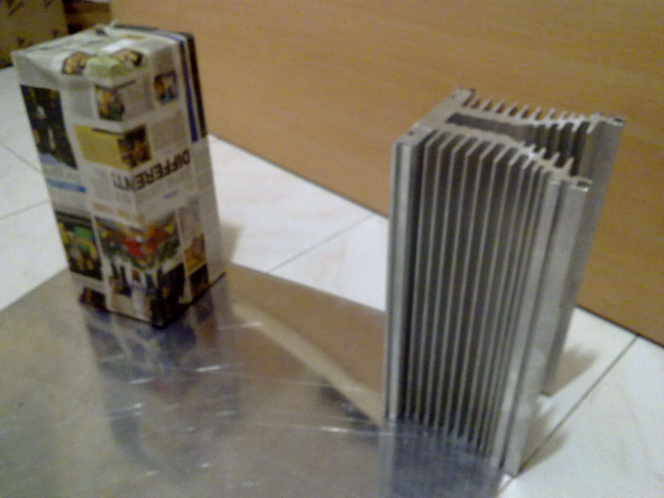
If still it heats up then some fan could be blowing air from bottom-up. But IMO that's distant but one possibility in well ventilated place as we face 47 deg C in summer.
By default in India it will be fan cooled ...we have 1~2 (depending on room size) 3.5 ft diameter ceiling fans .
And before any body laughs there is a 10-15c difference with them on an off (my measurement criteria is the stream of four letter expletives with hand on heatsink test)
.And before any body laughs there is a 10-15c difference with them on an off (my measurement criteria is the stream of four letter expletives with hand on heatsink test
)Indeed, one can stack 7 resistors in the proposed PCB and make it work, but to be honest it will look really crappy and odd. And I know TeaBag has a knack for really tidy and cool looking PCBs (his DCB1 was outstanding and also his F5T boards, from what I can see from Buzz's pics and hopefully in his next GB see it from close since I'll probably try both DiyStore and TeaBag boards) which I'm trying to take advantage of!
Keep a few things in mind. I started a PSU design on paper awhile back because people where asking me too. I wanted to keep it compact to work with the design parameters of the F5T convertible board, mainly one that will fit into a smaller chassis, and run at a possible lower bias. Designs are often full of compromises. This board can support F5Tv2-3 scale of projects and smaller requirements one's. I used a single resistor slot to save space, 35mm caps to save space. At the time, I did not know of ToeCutters failure to deliver, nor did Buzz, otherwise things may have gone differently. Prototyping boards and stuff is not a cheap effort, and often requires a bunch of people to be on the ball and commited. Enough said.
Several of my efforts for Power supplies are done point to point, with copper bus bar or wire and perf boards, and I encourage Buzz's purchasers to give it a go, or save parts for another project.
La Ode does the actual Gerber layout for all the boards, including Salas designs. He does good work.
Above all, smile. It's a hobby.
What do you think is the best? Low bias ~1-1.5A with 35V rails or high bias ~1.5-2A with 24V rails? Will bridge the F5t so the speakers will see double voltage any way. Will use 8 output devices per channel, F5 turbo V1. Will drive these speakers with it: Dynaudio Special Twenty-Five loudspeaker Measurements | Stereophile.com
Dissipation is already crazy with this.
Dissipation is already crazy with this.
- Status
- This old topic is closed. If you want to reopen this topic, contact a moderator using the "Report Post" button.
- Home
- Amplifiers
- Pass Labs
- F5 Turbo Circuit Boards