Ok, in that case how much lower do I want to go? Does a little go a long way?
What is the VGS required by your mosfets to conduct at around wanted current?
Set resistors for near enough and use pot to twidle
Keep pot influence to minimum is best IMO.
Take reading before you solder mosfets to board easy peasy and which way is clokwise in my particular pot question sorted + is my Jfet duda working question ansvered as well.
I will try to post Vgs vs Id curve for 12p20 tonight. I will add it to other curves of N channel fets. This should give folks an idea of what Vgs yields a given Id. This will help determine needed Id of jfets as BKsabbath suggested. Mine measured .5(sj74) and .6(sk170) across jfets Rs. This gava current needed to bia soutput fets to 1A. Reason you need more current for n channel jfet is higher Vth of P channel output fets. In this regard, FQA16n25c is closer match to Nchannel compliment than original 19n20c, by a smidge.
Last edited:
Hello all,
Ok thanks for the info. I have a mouser order going anyway, so I'll pick up some 10ohm 1W resistors to parallel as an option.
I don't have output devices yet and I'm not 100% on where they are coming from (more like 98%) so I would have to go by data sheet values.
I'd prefer not to have to desolder too many times, so the stuffing will continue with other components until outputs are finalized.
Hello all,
Ok thanks for the info. I have a mouser order going anyway, so I'll pick up some 10ohm 1W resistors to parallel as an option.
I don't have output devices yet and I'm not 100% on where they are coming from (more like 98%) so I would have to go by data sheet values.
I'd prefer not to have to desolder too many times, so the stuffing will continue with other components until outputs are finalized.
Very soon!
Stop as soon as she starts giggling, otherwise you've gone too far.in that case how much lower do I want to go?
She will be the judge, and definitely let us know when you have results.Does a little go a long way?
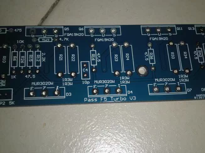
If we are looking down on the boards in the linked photo, as far as I can see Q5 and Q6 are still wrong. The double line is on the wrong side. The Emitter should point to the JFET's Drain and they don't. I had to draw them on a piece paper and turn it upside down to make sure.
I put them in according to the graphic on the board and had to unsolder them in the prototype V2 boards and turn them around.
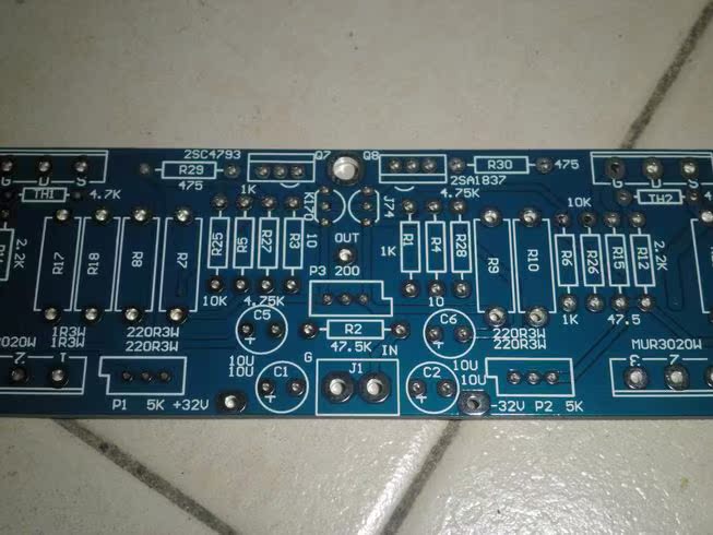
Secondly there are not enough ground holes. The link hole has no open ground hole to link to. Input ground wire, power ground wire, Link to where? double wires in one hole?
One more thing, in this new version, where is the hole for the speaker output? All the O/P holes in the input board are full, you wouldn't want to take the speaker wire from the N or P boards. You should connect the speaker wire to where the N and P boards connect together, at the input board, right?.
Rush
Rush,
I believe you are correct regarding Q5 & Q6.
Let me double check again.
I'll revert back soon.
Andy
Rush,
I believe you are correct regarding Q5 & Q6.
Let me double check again.
I'll revert back soon.
Andy
In regrds to the Link;
If using as SE you wire a link between 'Link' and Input Ground.
For balanced you wire a link between the two 'Link' terminals.
In regards to the Output and Ground Connections, the intention was that the Output connections are collected together at the chassis output terminals.
The Grounds are 'star' connected from the PSU.
If there is an error in my thinking I'm happy to be corrected.
Andy
I am pretty sure you want the input ground on the board and as well as the heavy ground going to the star ground. Could be wrong but that's the way I do it and I have seen other diagrams this way. Pretty sure the boards on the diyaudio store do it that way. An extra hole can't hurt.In regrds to the Link;
If using as SE you wire a link between 'Link' and Input Ground.
For balanced you wire a link between the two 'Link' terminals.
In regards to the Output and Ground Connections, the intention was that the Output connections are collected together at the chassis output terminals.
The Grounds are 'star' connected from the PSU.
If there is an error in my thinking I'm happy to be corrected.
Andy
An externally hosted image should be here but it was not working when we last tested it.
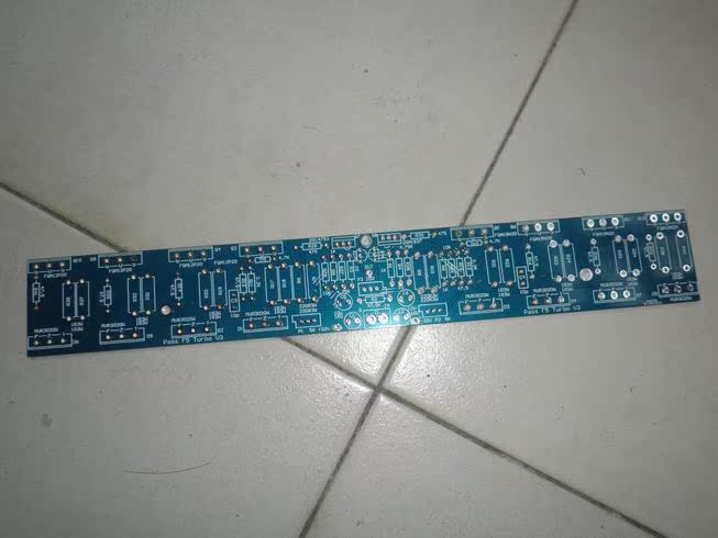
So please look over UKToecutter's boards here and check for errors. Otherwise they're ready to go. He has decided to have the boards available in the store instead of sending them out himself.
http://www.diyaudio.com/forums/pass-labs/206756-f5-turbo-circuit-boards-134.html#post3004341
Here is his spreadsheet for ordering boards.
https://docs.google.com/a/crozone.c...UAE2eGAZdExKMzBJNEluSTZ1LVg2LVJnN2xyeUE#gid=0
Problem is that the boards are a bit different now, but to me it seems easy to figure out what people want. These are the assumptions I made:
First categories are Input Boards and Balanced Input Boards. It would seem that they are now the same thing, ie now a double board with the scored center line?
So it seems we could combine the categories, and for each 2 old input boards requested put 1 new Input Bd. And for each balanced board requested 1 new Input Bd.
Next category is Output Boards.
the old Output Bds worked for both P and N channels. If someone ordered 2 then its pretty safe to assume that they wanted one N and one P? I note that all the orders are for an even number, so I think its safe to assume that they want half P and half N.
Hmmmm? Combo boards? And Single boards? Now that we have boards with only 2 positions, maybe we don't need singles? Maybe just cut the number in half , then make half P and half N?
I think we'll create a New Board Request spreadsheet. And leave the original, and ask you people to confirm that what you put on the NBR spreadsheet is correct, and that you're still interested. Its been a while so confirmation of interest is good..
We'll get to it soon
Mark
Here is the info on the boards to be sold at the store.
Rush
Yes, We're working with UKToecutter. So far his boards fit the Universal Mounting Standard. Now he's debugging them. Since the general concept has been/is being tested
he is quite confident they'll be right. We'll Shortly update Toecutter's spreadsheet and announce it here when you should go review the spreadsheet and confirm your interest.
Mark
he is quite confident they'll be right. We'll Shortly update Toecutter's spreadsheet and announce it here when you should go review the spreadsheet and confirm your interest.
Mark
- Status
- This old topic is closed. If you want to reopen this topic, contact a moderator using the "Report Post" button.
- Home
- Amplifiers
- Pass Labs
- F5 Turbo Circuit Boards