You could build a V2......
Using the combo board, right?
But what if I use, say... 8 single output boards side by side, with less space between them, to build v3?
Uk, do you have any idea of prices?
It seems I won't be able to use the diodes, right? There won't be enough room to place the two output boards on top of the other
I was thinking that you should try a v2 with the all-in-one boards. There should more than enough room to use the diodes as well. I haven't seen the dimensions of the board lately, but I can't imagine that the overall height with the TO-247 packages on the top an bottom rows is more than approximately 120mm.
But what if I use, say... 8 single output boards side by side, with less space between them, to build v3?
You don't have enough heatsink to do that.
You don't have enough heatsink to do that.
What if I lower bias? Also I intend to use Toshiba mosfets... (don't know whether this makes a difference, though)
That chassis look like it could handle a F5v2 easily.
Mwoah.
It means you boys are underestimating the heatsink requirements.
Read the manual : full Class A operation with 32V rails implies +100W dissipation per channel.
Papa's words : 0.4V across a 1 ohm source resistor, is 0.4A.
8 source resistors in a V2 makes 3.2A total => 1.6A bias, times 32V times 2 makes >100W heat. (~40W continuous Class A)
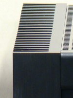
185 High x 430 Deep translates to two heatsinks on each side of roughly 200mm x 150mm each.
Judging from the geometry on the picture, the heatsink rib height is between 1.75" and 2", with a 0.2" thick base.
The rib height is ok, but i count only 14 ribs on each side.
Means that the 430mm case depth promises lots of space for transformers and caps, but the heatsinks are not impressive.
Read the manual : full Class A operation with 32V rails implies +100W dissipation per channel.
Papa's words : 0.4V across a 1 ohm source resistor, is 0.4A.
8 source resistors in a V2 makes 3.2A total => 1.6A bias, times 32V times 2 makes >100W heat. (~40W continuous Class A)
185 High x 430 Deep translates to two heatsinks on each side of roughly 200mm x 150mm each.
Judging from the geometry on the picture, the heatsink rib height is between 1.75" and 2", with a 0.2" thick base.
The rib height is ok, but i count only 14 ribs on each side.
Means that the 430mm case depth promises lots of space for transformers and caps, but the heatsinks are not impressive.
jacco. thats a nice rule of tomb")
take forinstance heatsink USA's 10.80" profile. in 6" lenght. 2 of them is good for a little over 100W. but a heat spreader is nice to have. the baseplate just don't do a good job. i got this running here right now. and the ends of the heasinks just dont get hot. but senter is about 50C. this is on F5 dual outputs pulling ~85W pr ch.
take forinstance heatsink USA's 10.80" profile. in 6" lenght. 2 of them is good for a little over 100W. but a heat spreader is nice to have. the baseplate just don't do a good job. i got this running here right now. and the ends of the heasinks just dont get hot. but senter is about 50C. this is on F5 dual outputs pulling ~85W pr ch.
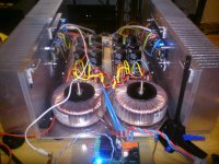
I looks like the MOSFETs are not very well positioned on the heatsinks to minimize temperature rise at the MOSFETs. Ideally, the MOSFETs would be centered about 5 inches apart. Use one of the heatsink design tools, such as NatSink to verify this.
Unfortunately, off-the-shelf F5 boards do not give you the ideal spacings, but you could do point-to-point wiring for the MOSFETs.
have tryed that. no the fets is bettor of mounted little lower. the heat is rising. so mount them a little below center.
the heat on the bottom and top of the heatsink are now very close.
Last edited:
the ends of the heasinks just dont get hot. but senter is about 50C.
Your output devices are too close apart, and mounted on one side of the heatsink.
With all the heat injected in a small area and having to travel all across the heatsink, practical use is limited, didn't expect just 85W though.
The 10mm base thickness isn't much help if the road is long, the second output device is also keeping the heat from the first one to migrate.
With the four output devices spread evenly across the two heatsinks, i'd expect a duo to handle much more, closer to 150W.
Good example though, just think what the outcome would be like with a 5mm base thickness

Last edited:
Your output devices are too close apart, and mounted on one side of the heatsink.
With all the heat injected in a small area and having to travel all across the heatsink, practical use is limited, didn't expect just 85W though.
The 10mm base thickness isn't much help if the road is long, the second output device is also keeping the heat from the first one to migrate.
With the four output devices spread evenly across the two heatsinks, i'd expect a duo to handle much more, closer to 150W.
i know. that's why a heat spreader is a nice thing to have
yes, they will handle a lot more if the heat is spread.
i'am thinking of moving the inner mosfets and gate stoppers out with cables.
will see. it's realy no need in this set up right now.
5mm baseplate? hmmm. frying eggs in the midle and cooling beer at the end
Last edited:
Btw, checked out Daniel's amp case after my blabber.
http://www.htforum.com/vb/showthrea...OR-NASHVILLE-A77iS!-PRATICAMENTE-NOVO!!-FOTOS!
In the other pictures it looked like two heatsinks in series, turned out to be just a scratch, right in the middle of the heatsink.
The 430mm depth likely includes the handles, without them and the front plate, the heatsinks are something in the order of 380mm wide, with a total of 16 ribs.
I'd be surprised if they handle more than 85W at 25C temperature rise, much less would not be a shock.
(really pretty heatsinks for a Class AB amp though)
Last edited:
Your output devices are too close apart, and mounted on one side of the heatsink.
With all the heat injected in a small area and having to travel all across the heatsink, practical use is limited, didn't expect just 85W though.
The 10mm base thickness isn't much help if the road is long, the second output device is also keeping the heat from the first one to migrate.
With the four output devices spread evenly across the two heatsinks, i'd expect a duo to handle much more, closer to 150W.
Good example though, just think what the outcome would be like with a 5mm base thickness
How thick should the heat spreader be , 10 mm sufficient ?
Depends on the heatsink geometry, the heat concentration, fan blown or natural convection.
The heatsinks i use for the ExtremA's, my daily use amps, have 2-3/8" ribs and a 0.8" spreader plate.
Only ~6.25" wide heatsink, fan blown, but handle 260W dissipation each (and i can fold a slice of cheese across).
10mm is a good start, more for high-density or high-performance fins.
Example of a getting Jiggy with a Thicky =>
Attachments
A 10mm back plate is effective in spreading the heat out to the fins within a 100mm radius.
Fins beyond that 100mm radius run cooler than the area directly behind the hot device.
10mm thickness allows two devices spaced at 175 centre to centre and 80mm up from the bottom to get very good dissipation from a sink 350mm wide by 180mm high.
That 10:1 ratio mentioned in the first sentence is a good rule of thumb. It also applies to the fins.
- Status
- This old topic is closed. If you want to reopen this topic, contact a moderator using the "Report Post" button.
- Home
- Amplifiers
- Pass Labs
- F5 Turbo Circuit Boards