No apologies needed. No links need to be broken. You only need to ability to ground the trace I described, relegating the two amplifiers to single ended mode.Ah...
I see it now.
We need to break the link between the wiper of P3 & P6 to set up. Is that right?
If so, my apologies to you Iqhuam.
I'll find a suitable switch
Andy
Gentlemen,
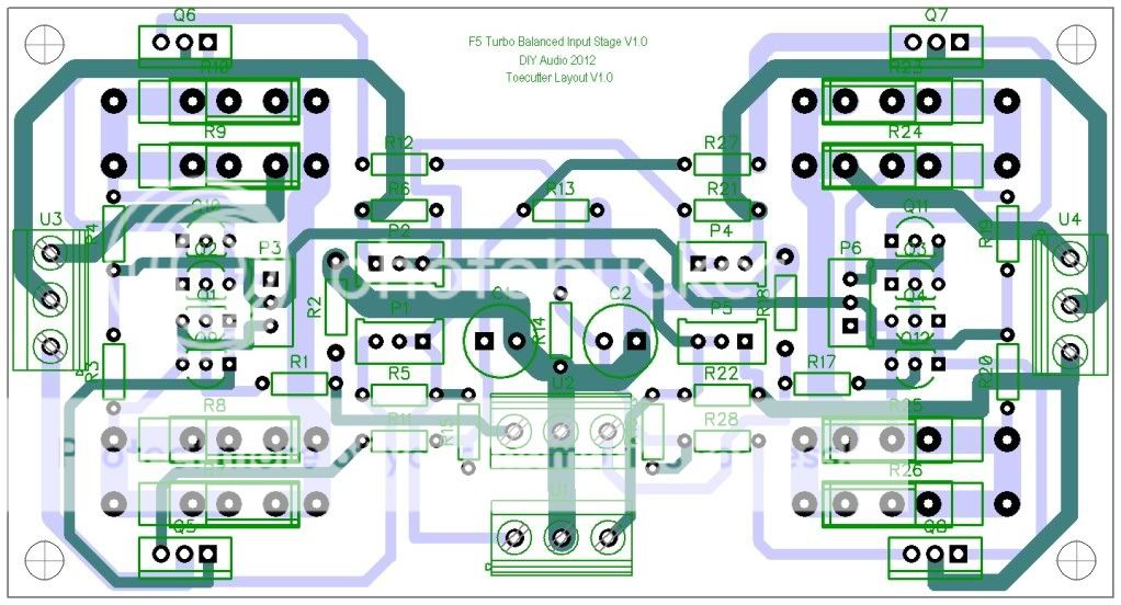
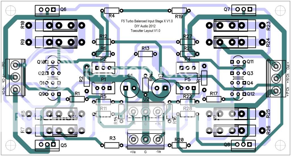
I present the V3 Balanced input stage board.
I'm sure I can get it a bit smaller. It's currently 120mm x 64mm so smaller than 2 x SE Input stage boards.
Andy
Hi Andy,
please don't kill me, I know that this is already complicated enough. BUT as you are there, why not X' it?
Hi Andy,
please don't kill me, I know that this is already complicated enough. BUT as you are there, why not X' it?
JBL
Perhaps you can enlighten me.
What do you mean by 'X' it?
Couldn't find this anywhere... what is the ETA of the boards? Should we be collecting parts already?
You can get the parts right away, but waiting for the boards to be ordered means that there won't be any changes to the board that might imply different pin spacing for some of the parts. After the boards are ordered we'll have probably a couple of weeks until they are done, so you'll hav plenty of time then I think.
JBL
Perhaps you can enlighten me.
What do you mean by 'X' it?
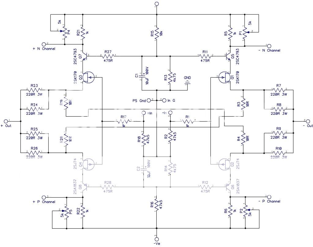
The beginning of the F5X thread can be found here, which has some good information (and a schematic) on the balanced "X" approach. EUVL discusses grounding the X to separate the balanced circuit into (2) single ended ones for initial setup.
Here is another discussion on the need (or lack thereof) of P3 in a floating "X" arrangement. It sounds like the "X" has the benefit of additional cancellation for lower THD.
There was a GB for a specific version of the F5X (non-turbo) which included a specially design case, power supply, protection board, etc. This group buy has already come and gone, and those boards could not be used for someone wanting to build a F5 Turbo.
I just posted the information to give you an idea how the "X" differs from the balanced schematic shown in Nelsons F5T article. I'm happy with the layout of your boards, but others were asking.")
I just posted the information to give you an idea how the "X" differs from the balanced schematic shown in Nelsons F5T article. I'm happy with the layout of your boards, but others were asking.
There was a GB for a specific version of the F5X (non-turbo) which included a specially design case, power supply, protection board, etc. This group buy has already come and gone, and those boards could not be used for someone wanting to build a F5 Turbo.
I just posted the information to give you an idea how the "X" differs from the balanced schematic shown in Nelsons F5T article. I'm happy with the layout of your boards, but others were asking.
I just read some more on the X,
Seems to me that a couple of jumpers might do it.
I'm looking at it now.
Horio
Tell me I'm wrong (but only if I am).
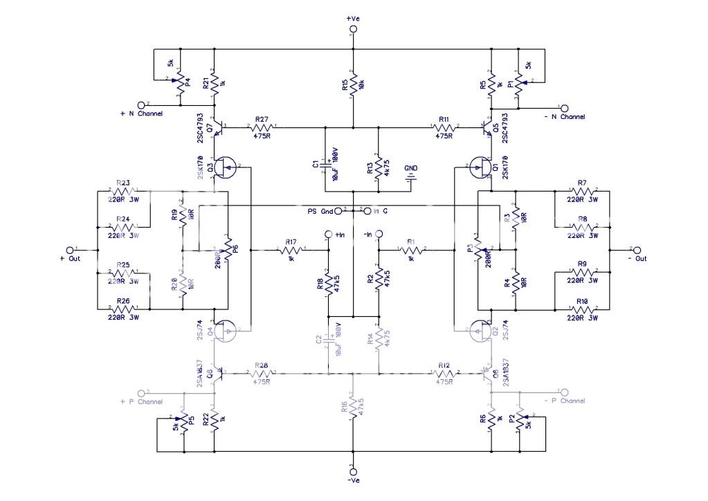
If you wanted to build an X it seems to me that you need to remove the track between R3 & R4 and R19 & R20. A track (or wire) then needs to run between R3 & R20 and R4 & R19. This is assuming P3 & P6 are not in circuit.
Am I missing something?
Andy
Tell me I'm wrong (but only if I am).
If you wanted to build an X it seems to me that you need to remove the track between R3 & R4 and R19 & R20. A track (or wire) then needs to run between R3 & R20 and R4 & R19. This is assuming P3 & P6 are not in circuit.
Am I missing something?
Andy
Horio
I haven't read the whole thing but it seems that there are already plans for a GB of the X layout.
In which case I don't want to re-invent the wheel, so to speak.....
The EUVL F5X is a single board (except for the power supply) and requires a particular size of heatsink and case. There is not as much flexibility is packaging as for the multiple board amplifier "family" using your boards.
I have been doing SPICE simulations of the X-topology vs Nelson's balanced option. The distortion figures are about the same. Both will work with single-ended inputs, but the output voltage is about 30% lower on the side with the grounded input. Thus, I do not see a strong reason to worry about implementing the X, versus Nelson's floating node. One switch to ground the node converts the system to a pair of unbalanced amplifiers.
- Status
- This old topic is closed. If you want to reopen this topic, contact a moderator using the "Report Post" button.
- Home
- Amplifiers
- Pass Labs
- F5 Turbo Circuit Boards