Hi Paul,
IIRC they were about $5.00 each part so $10 a pair,I have ordered from him ,He's a good guy and parts are good, I have understood the genuine parts have some copper right where the pins go into the plastic case,some that are questionable do not have,they are silver all the way into the case,he ships pretty fast too!
NS")
Thanks for the responses!!!!!!
For the 2SK170 and 2SJ74, 2 pair for $200. I sent him another e mail to see if that was in US$. Hope not. But yes, he seems to be the MAN.
Wonder where he procured them?
Thanks
Paul
IIRC they were about $5.00 each part so $10 a pair,I have ordered from him ,He's a good guy and parts are good, I have understood the genuine parts have some copper right where the pins go into the plastic case,some that are questionable do not have,they are silver all the way into the case,he ships pretty fast too!
NS
Thanks and ordered
Thats great. I put a lot of time in on this so far. I hope someone will Mfg them soon. I think Mr Pass has several PCB designs done around this.
Although, I did order 4 of Rod's (ESP) MOSFET boards also.
While we are on the subject. Question, I have two mono blocks with 3LM3886 per chn I am in the middle of finishing. I was wondering since they have 18-0-18vac 600va torrids in each. Would the TORRIDS be better utilized using the F5c boards than the 3*LM3886. It would be an easy swap out, but the heat sinks are not quit as large. I have noticed several other F5c builds with just the single tranys are not getting that hot?
Not sure of the benifit trade off would be.
Thanks
Paul
IIRC they were about $5.00 each part so $10 a pair,I have ordered from him ,He's a good guy and parts are good, I have understood the genuine parts have some copper right where the pins go into the plastic case,some that are questionable do not have,they are silver all the way into the case,he ships pretty fast too!
NS
Thats great. I put a lot of time in on this so far. I hope someone will Mfg them soon. I think Mr Pass has several PCB designs done around this.
Although, I did order 4 of Rod's (ESP) MOSFET boards also.
While we are on the subject. Question, I have two mono blocks with 3LM3886 per chn I am in the middle of finishing. I was wondering since they have 18-0-18vac 600va torrids in each. Would the TORRIDS be better utilized using the F5c boards than the 3*LM3886. It would be an easy swap out, but the heat sinks are not quit as large. I have noticed several other F5c builds with just the single tranys are not getting that hot?
Not sure of the benifit trade off would be.
Thanks
Paul
hi Paul,
Thats great. I put a lot of time in on this so far. I hope someone will Mfg them soon. I think Mr Pass has several PCB designs done around this.
Although, I did order 4 of Rod's (ESP) MOSFET boards also.
While we are on the subject. Question, I have two mono blocks with 3LM3886 per chn I am in the middle of finishing. I was wondering since they have 18-0-18vac 600va torrids in each. Would the TORRIDS be better utilized using the F5c boards than the 3*LM3886. It would be an easy swap out, but the heat sinks are not quit as large. I have noticed several other F5c builds with just the single tranys are not getting that hot?
Not sure of the benifit trade off would be.
Thanks
Paul
Hi Paul,
message didn't post.....
I am sure there are ways around J74 problem,seems like with the demand someone would make them?
As far as the lm3886,I replaced mine with F5,F5c,F5T and a (2) 10 lm3886 550Watt amp's for 2 Xoc1's sub's ,I did like the F5's better than lm3886 i was using for hi,mid,bass,I run them balanced threw a DEQ2496 to 2 DCX2496 (4 way)all digital to the amps,It makes a fine noise,lol.try it out a nd see if it sounds better to your ears,It's hard to tell you what to do with your system as all systems are different and so is our EARS,lol. I hope the F5 will be a keeper for you ! I almost have a 6 fet BA-3 ready ,I would like to try it in the bass amp position,I like the punch from FETs!
Best too Ya!
NS
Hi Everyone,
I have been reading all the list sites looking for a replacement to the FQA12P20 Mosfet and FQA19N20 Mosfet in the F5T and I am wondering if using a IC with a higher current draw such as 36a instead of the 19a in the FQA19N20 and adding some extra beef to the power supply would work? Or, using a IC with a relational total wattage like a 900v 6a Mosfet to replace the FQA19N20 200v 19a Mosfet which have a difference of .5w of power. I could totally be looking at this problem wrong and would greatly appreciate any assistance.
Thank you,
Jesse
Hope it's not TOO hot in Texas as I'm flying to Houston in the morning!!!
Wait , What ..! you're alive ..................
Wait , What ..! you're alive ..................
Ha ha...
Yes, very much so.
But IT IS hot in Texas and VERY humid.
Flying back to the UK tomorrow evening where the temperature is far more moderate.
Progress for the Far East
Hi Buzz and everybody in the thread,
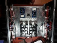
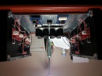
the second channel is complete and I am now preparing for the final layout.
Can you please tell me raffly the dimension of the toroids? I am palnning to buy from the store the new risers having +/- height of 120 mm and large 200 . I think is enough for the trafos but I need your advise, as usual
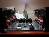
In the pics you can see the final layout. Using the risers all the PSU section and the 2 soft start will be elevated by 120mm.
I have also a doubt about the earth bridge. This will be the only common part for the channel. Should be better to have one bridge dedicate to each PSU or is useless? Thanks and regards,
Emeyuoi
Hi Buzz and everybody in the thread,
the second channel is complete and I am now preparing for the final layout.
Can you please tell me raffly the dimension of the toroids? I am palnning to buy from the store the new risers having +/- height of 120 mm and large 200 . I think is enough for the trafos but I need your advise, as usual
In the pics you can see the final layout. Using the risers all the PSU section and the 2 soft start will be elevated by 120mm.
I have also a doubt about the earth bridge. This will be the only common part for the channel. Should be better to have one bridge dedicate to each PSU or is useless? Thanks and regards,
Emeyuoi
Attachments
120mm should give you enough hieght, as I think the biggest transformer is about 3.5". Diameter wise, you are loooking about double that.
Thanks Buzz. You are always available for good advises
Looking on the thread of 6L6 relevant to the build guide for the F5T V2 in the first page he show the transformer near to a CD but I can't see how much is high and if is a 600VA as I order. Anyway as you say I should have a lot of room.
Cheers
PS: sorry, one of the picture is upside/down... here in the correct side
Attachments
The transformer used in my build is 143mm diameter x 79mm tall. It is 600VA.
Hi 6L6, thanks for the info and congratulation for the guide... very useful
Cheers
Thank you.
One of these days, when I get a bit of time to apply to this, I will actually get the guide finished.

PS: sorry, one of the picture is upside/down... here in the correct side
emyeuoi
Looks like we are pretty much at the same stage, I am using the same Boards as you. and only one PSU by Tea.
I had blown one channel of my amp and had a ground loop, members here recommended I get teas boards. So will soon rewire everything with them.
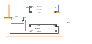
But will closely watch your progress, The Wiring scheme I am going to have to think hard about as not to make the same mistake as last time! I notice that the PSU has 3- 3+ and 6 Ground connections on the output, Very usefull so will see how you wire them as realy am not sure of the best way.
Anyway nice work
Last edited:
emyeuoi
Looks like we are pretty much at the same stage, I am using the same Boards as you. and only one PSU by Tea.
I had blown one channel of my amp and had a ground loop, members here recommended I get teas boards. So will soon rewire everything with them.
But will closely watch your progress, The Wiring scheme I am going to have to think hard about as not to make the same mistake as last time! I notice that the PSU has 3- 3+ and 6 Ground connections on the output, Very usefull so will see how you wire them as realy am not sure of the best way.
Anyway nice work
Hi Rixsta, sorry for the late reply. I read on the threads that you have a loop ground problem. I am just progressing on my first build and I can't help you in detail but as I understand from Buzz and reading in various threads in the forum the only way to avoid ground loops is having only one star ground on the Front End board. In this way the 6 ground connections on the PSU unfortunatelly are not usefull and you have to connect all the ground cables in the same point and back to the PSU with only one (big size) ground cable.
I hope that my understanding is correct and this is best way and I am sure that somebody in the forum will give us all the support
Anyway, I will keep post the progress... All my best for your re-wiring
emyeuoi
Thanks emyeuoi
Im just in the process of sorting some things and wiring up, the diagram above as reference for the boards, and also will drill a hole where you have as thats a great idea
I see what you mean about having to wire them all to the same point as star ground.
I know this point can be at the Front End boards but thought it might be able to be at the PSU output too.
Anyway on with the progress.
- Status
- This old topic is closed. If you want to reopen this topic, contact a moderator using the "Report Post" button.
- Home
- Amplifiers
- Pass Labs
- F5 Turbo Circuit Boards