Hi
I build the F5 turbo with low rails +/- 15V for driving a low impedance ribbon speaker.
Everything looks fine bandwidth 750Khz -3dB and I get about 35A from the output in this configuration.
I use 4 sets mosfets from IR the IRFP240 and IRFP9240 and 0,235 Ohm source resistors.
The fronted is the same as the F5 with 100 Ohm parallel in the feedback loop.
Now the problem if I feed the amplifier 100Khz and on the output the voltage rise above 20Vtt then the output collapse and the fets drawing lots of current about 10A each.
It doesn't mind if I load the output with a resistor or not.
What could be the problem.
I tried capacitors on the feedback resistors to reduce the bandwidth to 100Khz use input filter and 1N from drain to gate.
Nothing helps.
Rob
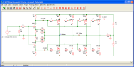
Attachments
Hi,
Unability of the front end to supply enough current to properly swing the output mosfet's gate capacitance at such high freq ? this leading to what class D people call shoot through, ie N and P channel mosfets conducting too much at the same time, ie shorting V+ to V-
Regards,
--
stéphane
Unability of the front end to supply enough current to properly swing the output mosfet's gate capacitance at such high freq ? this leading to what class D people call shoot through, ie N and P channel mosfets conducting too much at the same time, ie shorting V+ to V-
Regards,
--
stéphane

Hi stéphaneHi,
Unability of the front end to supply enough current to properly swing the output mosfet's gate capacitance at such high freq ? this leading to what class D people call shoot through, ie N and P channel mosfets conducting too much at the same time, ie shorting V+ to V-
Regards,
--
stéphane
Should I leave it like that and pay no attention to it or can it cause problems.
Rob
It could also be due to different things
But if my take is right then no it cant stay like that, you will burn your output stage sooner or later
But if my take is right then no it cant stay like that, you will burn your output stage sooner or later
Ok then a lot of people building the F5 turbo will have problems.
Hope that someone else has a bright idea how to tackle this problem.
Rob
Hope that someone else has a bright idea how to tackle this problem.
Rob
Is 20Vtt the same as 20Vpp?
If so, then an output of 20Vpp should not be clipping in an amp fed from +-15Vdc when there is insignificant load current.
If so, then an output of 20Vpp should not be clipping in an amp fed from +-15Vdc when there is insignificant load current.
Hi
Vtt = Vpp.
No it's not clipping thats at 30 Vpp.
I go back to 2 fets and see if I still have this problem.
And Jacco I raise Vds and see if it helps.
Can somebody else check out if he has this problem?
Rob
Vtt = Vpp.
No it's not clipping thats at 30 Vpp.
I go back to 2 fets and see if I still have this problem.
And Jacco I raise Vds and see if it helps.
Can somebody else check out if he has this problem?
Rob
Last edited:
I would try higher Source resistor values, and I would also try RC networks
in parallel with R7 and R8. The RC should be 470 ohms or so in series with
1 uF, and see what you get.
😎
in parallel with R7 and R8. The RC should be 470 ohms or so in series with
1 uF, and see what you get.
😎
Hi Nelson
Try the RC network with 470 ohm and 220 ohm but no help.
You told in the turbo paper that you can run it without source resistors so why go higher.
Want to drive 0,4 ohm.
Is it possible that the IRFP9240 from international rectifier is the problem?
Rob
Try the RC network with 470 ohm and 220 ohm but no help.
You told in the turbo paper that you can run it without source resistors so why go higher.
Want to drive 0,4 ohm.
Is it possible that the IRFP9240 from international rectifier is the problem?
Rob
I have tried these various and sundry, but I know I didn't run your
circuit up too 100 KHz at power.
You want to try higher Source resistance because it might give us a clue.
If it's not related to that, then in might simply be inadequate drive,
requiring parallel input devices as outlined.
It is possible that the IR parts are at fault, the N channel IR part has
about 50% more Ciss and the P channel 50% more than that. In
addition, the P channel device has what is referred to as the "IR P
distortion" in which the transconductance shelves.
Even so, are you planning on operating this as an audio amplifier?
😎
Hi Nelson
Ok I try the source resistors.
Yes it's for driving a true ribbon speaker
At the moment I use it as a driver with the 610 and 9610 to drive 4 sanken 2SA1295 and 2SC3264 and it looks promising.
Rob
Ok I try the source resistors.
Yes it's for driving a true ribbon speaker
At the moment I use it as a driver with the 610 and 9610 to drive 4 sanken 2SA1295 and 2SC3264 and it looks promising.
Rob
I am struck by the possibility that the cross-current conduction you are
experiencing is the result of the Jfets operating beyond their bias to charge
the capacitance of the output devices so that there is a net increase in their
average current.
There is something you can try for this.
Connect the Source pins of the two Jfets together and increase the values
of the feedback resistors 100 ohms and 1Kohms. This will increase the
bias current and it will also put more local degeneration on the Jfets. From
there you can parallel Jfets for more current.
I think you still need to try raising the values of the Source resistors of
the output devices.
😎
Gosh maybe I am off base here if so Please forgive my Ignorance,If 20khz is the limit for some humans hearing,mine is 16.5khz,Why are you at 100khz anyway ,anything over 20khz is out of audible hearing,try cutting the freq bandwith down to 20khz or If you think you can hear it 22khz and see what it does,I agree with the posts,you can't have them both on at once,And it will burn up,
It's just my 2 cents,goodluck to you.
Regards,
NS
It's just my 2 cents,goodluck to you.
Regards,
NS
- Status
- Not open for further replies.
- Home
- Amplifiers
- Pass Labs
- F5 turbo problems