I have the skeleton of a Hafler DH-200 that I'm planning on using to host a Class-A amp, probably an F5 or BA-2.
Picture of a DH-200 as manufactured: http://i.imgur.com/mGy2k.jpg
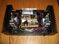
I'm basically starting with an empty chassis, except the output devices are still installed. There are 2x 2SK134 and 2X 2SJ49 per channel. I believe they are all still perfectly functional. I have a new IEC inlet socket, and new input and output connectors mounted by a previous owner.
Is there any point trying to modify either F5 or BA-2 to work with these FETs, or am I better off just using the IRF parts as per Nelson's design? I think the existing FETs are already matched.
If I was to go with the existing parts, what would I have to change to accommodate them?
Picture of a DH-200 as manufactured: http://i.imgur.com/mGy2k.jpg
I'm basically starting with an empty chassis, except the output devices are still installed. There are 2x 2SK134 and 2X 2SJ49 per channel. I believe they are all still perfectly functional. I have a new IEC inlet socket, and new input and output connectors mounted by a previous owner.
Is there any point trying to modify either F5 or BA-2 to work with these FETs, or am I better off just using the IRF parts as per Nelson's design? I think the existing FETs are already matched.
If I was to go with the existing parts, what would I have to change to accommodate them?
I did a test amp with the 2SK134 and 2X 2SJ49 mosfets, from a Erno Borbely B60 amp, for the outputs of a F5 and found it to sound very good. I'm planning to build an F5 using three pairs of the higher powered Hitachi's and cascode the jfets so I can use a higher voltage rail. Go for it. Just make sure of the pin outs of the mosfets. edit. Just saw post #2 after sending my reply. I don't know I think the heat sinks would be ok. If they get too hot just drop the bias point some.
Last edited:
shortly - one DH200 case is perfect for one F5 channel
Really? Why not 2 channels?
wimpy heatsinks
according to my (weak ) memory - you can't throw much more than 40W on each side
Ah. Maybe I should turn on those FETs and make some measurements.
wimpy heatsinks
according to my (weak ) memory - you can't throw much more than 40W on each side
Sniff... He called my heatsinks wimpy. Oh the shame.
")
I had those wimpy snks five years or even more
Looks like I'm getting about 0.45 degrees C per Watt with all 4 devices driven the same.
I'll let it cook a bit longer to be sure.
I don't like the design of these sinks, because they mount the devices on a thinner section that sticks out from the bulk of the Alu. I wonder if I mounted two IRF devices between the two big fins if it would work better.
The fins that mount the devices are about 8 degrees hotter than the external fins of the heatsink.
The fins that mount the devices are about 8 degrees hotter than the external fins of the heatsink.
I don't like the design of these sinks, because they mount the devices on a thinner section that sticks out from the bulk of the Alu. I wonder if I mounted two IRF devices between the two big fins if it would work better.
The fins that mount the devices are about 8 degrees hotter than the external fins of the heatsink.
After it stabilized, it looks like very close to 0.6 degrees per Watt at the hottest part of the heatsink. I think if I mounted devices closer to the radiating fins, the performance would be a little better.

With an "F-LH", 56w per channel dissipation with no problem.
https://sites.google.com/site/fabaudio/jlh-fabclassapoweramp
Good luck
https://sites.google.com/site/fabaudio/jlh-fabclassapoweramp
Good luck
... except the output devices are still installed. There are 2x 2SK134 and 2X 2SJ49 per channel. I believe they are all still perfectly functional. I have a new IEC inlet socket, and new input and output connectors mounted by a previous owner.
Is there any point trying to modify either F5 or BA-2 to work with these FETs, or am I better off just using the IRF parts as per Nelson's design? I think the existing FETs are already matched.
If I was to go with the existing parts, what would I have to change to accommodate them?
The end result would be different from an original F5 since the Lateral Mosfets of the DH-200 are quite different than the IRFP vertical mosfets.
The transconductance of the Lateral is about 5 times less than of the IRFP thus giving a lower OPEN loop gain. However, keeping 2 pairs of Lateral as in the DH-200 would give you a little more OPEN loop gain but still lower than F5. The Lateral mosfet are known to be specifically designed for audio use though.
For sure the 0.47 ohms source resistors of the mosfet can be reduced or even eliminated because of the matched lateral mosfets.
You can also try an alternative circuit such as:
http://www.diyaudio.com/forums/pass-labs/123640-f4-type-amp-but-gain.html#post1518771
However, I would increase the jfet current by reducing R3 and R4 (thus adjusting feedback resistors R24 and R25)...
Or even better use a proven working very good design:
http://www.diyaudio.com/forums/pass-labs/162042-f5-meets-buzquito.html#post2097690
This one I used and got even better sound result than my F5 (in my audio system).
Good luck
Fab
Last edited:
I installed a JLH in one of those. 15w@8 ohms ...+52 watts dissipation- laying your hand on it was somewhere between crikey hot and
-Mal
Yes it gets hot, but worse inside the box than outside. I just tested it with 54 Watts, and the temp stabilized at about 60 Celsius measured by infrared on the flange that mounts the devices. At that temperature, I was able to hold my hand against the external fins indefinitely.
Maybe my hands are unusual, but the infrared thermometer claimed the external fins were above 50 Celsius. It also claims the inside of my mouth is 37 Celsius, so I think it's basically believable.
Assuming I went with the IRF devices, I wonder if I would be able to hear the difference between 1.3A and 1.0A bias. Knowing me, maybe not.
- Status
- This old topic is closed. If you want to reopen this topic, contact a moderator using the "Report Post" button.
- Home
- Amplifiers
- Pass Labs
- Hafler DH-200 to host F5 or BA-2 ?