I read the last part of this thread with interest. Although I have not the theoretical knowledge to provide answers to that is raised in this thread. But I understand that others reply to this topic affects the questions I seek answers to.
My starting point is the following: I have previously built F5 turbo V3 with cviller PCB. These PCB are no longer available, so I have chosen the only available option from Jims Audio: F5Mosfet pure class A thick turbo V3 turbo
With these PCB I want to build an F5 turbo where the purpose is to extract the maximum Class A power. I have the following “base” which in this thread will determine how far it is possible to satisfy my original desire: Maximum class A output.
I have acquired the following to add the above PCB:
Transformers: Two 500VA with secondary windings 2x25V AC.
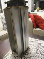
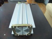
Heatsinks: A massive cooling tunnel with fan (3350 mm long,unfortunately I have no other data to show, but see attached photos). Both the MOSFET and MUR 3020 will be mounted on this heatsink. MOSFET are IRFP
Ihquam wrote:
Of course the Turbo V1 bias could be increased to 1.5 amps per MOSFET in order to have 70 watts class-A, but that would dissipate about 200 watts at idle.
If this can be "transformed" to a F5 turbo:
This output would be fine for me, so it is a good “start”(but I wish more if possible).
Ihquam wrote:
I forgot to mention, that the previous curves are with 1R0 source resistors (not 0R5) with MOSFET bias of 0.5A.
My answer to Ihquam is: Will 1R0 be the value for the source resistance mentioned in your post 553 also be the “right” one for my wishes of 70 W, or will another value be a better choice? To dissipate 200W with the heatsink- tunnel I think (hope) will be an ok challenge.
Ihquamwrote:
With actual tests (not SPICE) I have found that a bias of about 1.25A through the MOSFETs is needed to get the THD below .005%. The voltage across the 0R5 source resistors is about 0.525 volts
To keep the THD below .005% is also what I go for, and this is taken care of with bias of 1.5A I understand.
Joesch asked this question
24v secondarys for f5 turbo, right?
Buzzforb answered:
Depends. 50W yes. 100W, you need 32V secondary.
Does this mean that my transformers with 2x25V AC cant meet my wishes to have 70 W?
If not, any idea what to do? For my self I se a possibility to give my transformer added windings to give more AC out. 2x32V AC?? Will more windings be an absolute thing to do if I want to achieve my goals??
Labjr asked:
Would 800 VA be enough for 100 watts?
Buzzforb answered:
For 100W V3, you are gonna be dissipating about 250W per channel. I would think 800 per channel or monoblock is more ideal.
As far as I can see that this speaks against my wishes to have more than 70 W class A?
So, can anyone give me a good answer to all my questions to reach more than 50W and with 70 W class A as my “best wish”?
Eivind Stillingen
My starting point is the following: I have previously built F5 turbo V3 with cviller PCB. These PCB are no longer available, so I have chosen the only available option from Jims Audio: F5Mosfet pure class A thick turbo V3 turbo
With these PCB I want to build an F5 turbo where the purpose is to extract the maximum Class A power. I have the following “base” which in this thread will determine how far it is possible to satisfy my original desire: Maximum class A output.
I have acquired the following to add the above PCB:
Transformers: Two 500VA with secondary windings 2x25V AC.
Heatsinks: A massive cooling tunnel with fan (3350 mm long,unfortunately I have no other data to show, but see attached photos). Both the MOSFET and MUR 3020 will be mounted on this heatsink. MOSFET are IRFP
Ihquam wrote:
Of course the Turbo V1 bias could be increased to 1.5 amps per MOSFET in order to have 70 watts class-A, but that would dissipate about 200 watts at idle.
If this can be "transformed" to a F5 turbo:
This output would be fine for me, so it is a good “start”(but I wish more if possible).
Ihquam wrote:
I forgot to mention, that the previous curves are with 1R0 source resistors (not 0R5) with MOSFET bias of 0.5A.
My answer to Ihquam is: Will 1R0 be the value for the source resistance mentioned in your post 553 also be the “right” one for my wishes of 70 W, or will another value be a better choice? To dissipate 200W with the heatsink- tunnel I think (hope) will be an ok challenge.
Ihquamwrote:
With actual tests (not SPICE) I have found that a bias of about 1.25A through the MOSFETs is needed to get the THD below .005%. The voltage across the 0R5 source resistors is about 0.525 volts
To keep the THD below .005% is also what I go for, and this is taken care of with bias of 1.5A I understand.
Joesch asked this question
24v secondarys for f5 turbo, right?
Buzzforb answered:
Depends. 50W yes. 100W, you need 32V secondary.
Does this mean that my transformers with 2x25V AC cant meet my wishes to have 70 W?
If not, any idea what to do? For my self I se a possibility to give my transformer added windings to give more AC out. 2x32V AC?? Will more windings be an absolute thing to do if I want to achieve my goals??
Labjr asked:
Would 800 VA be enough for 100 watts?
Buzzforb answered:
For 100W V3, you are gonna be dissipating about 250W per channel. I would think 800 per channel or monoblock is more ideal.
As far as I can see that this speaks against my wishes to have more than 70 W class A?
So, can anyone give me a good answer to all my questions to reach more than 50W and with 70 W class A as my “best wish”?
Eivind Stillingen
Attachments
Eivind -
If using the Jim's boards you will have enough output devices to handle most loads. Good.
Your 25V transformers will rectify to 35V, and then lose ~2V for the diodes, giving 33V rails.
With 33V rails you will probably be able to swing within a volt or two, so let's say the amp will make it to 31V, giving you a total peak-to-peak voltage swing of 62V.
62V (pk-pk) * .3535 = 21.9V RMS
Amplifier power = V RMS^2/load
21.9^2= 479.6
479.6/8ohm = 59.95W
479.6/4ohm = 119.9W
The way I see it, you have the proper pieces to make your desired power. Also Class-A watts sound a lot bigger than their measured performance, this will be a very powerful amp.
A few suggestions -
One transformer and one PSU board per channel. The diyAudio PSUv3 pcb is perfect for this.
You will need some kind of thermal shut-off, as a fan failure will almost certainly destroy your amp when it overheats.
6L6. Thank you. You hit excatly the informations I was searching for, and you gave the theory behind it in a very understandable way, even for an amateur like me. Yes, I ment to use one PSU for each channel and a thermal cut off.
In my post I forgot to tell about 4 or 8 ohm, but you also gave an answere to that.
If you also can recommend a R source and a bias ( 1R0/1.5A??) this is "fullfilled".
Eivind Stillingen
In my post I forgot to tell about 4 or 8 ohm, but you also gave an answere to that.
If you also can recommend a R source and a bias ( 1R0/1.5A??) this is "fullfilled".
Eivind Stillingen
Build it as per the V3 schematic, and remember to include C3, C4 (1000pF 50V) You might want to increase the gate resistors to 150-470R, to help keep from HF oscillation. This is an extremely wide-bandwidth design, and some HF limitation (up around 200Khz or so) helps it from frying itself. The increase ing Gate resistor value and the C3, 4 caps do this)
The 1.0ohm resistors are fine, there are 2 in parallel, so it's really 0.47R 6W
As for bias, start with .35V across the source resistors. Increase from there until one of these things happen - 1) your output devices reach 65C, 2) your current really takes off because you've got enough to get the diodes conducting, 3) you have 250W total bias/channel (which is 1/2 of your transformer current)
Last edited:
Anwerk
I'm a little surprised at the statement that the air-cooled tunnel will give uneven cooling of the different output transistors, but I have no practical experience with such a solution. Can you give a more detailed explanation of what happens? Is this problem so great that it should be discouraged?? I also mentioned that I had planned that also MUR 3020 to be placed on the same cooling profile.
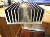
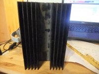
I also have the ability to use passive cooling. I have four pieces 1000 mm long profiles. They are 120 mm wide, the fins are 42 mm. See attached pictures. I imagine that a possible solution could be to connect three or four profiles together. Interconnection can be done by fasten yhem on a 3 mm aluminum plate. Does anyone have suggestions for such a passive solution adapted to a 70 W class A F5 turbo as I have described in my earlier post. I imagine 2x mono build and that such a cooling plate must necessarily have some and perhaps considerable height.
Eivind Stillingen
I'm a little surprised at the statement that the air-cooled tunnel will give uneven cooling of the different output transistors, but I have no practical experience with such a solution. Can you give a more detailed explanation of what happens? Is this problem so great that it should be discouraged?? I also mentioned that I had planned that also MUR 3020 to be placed on the same cooling profile.
I also have the ability to use passive cooling. I have four pieces 1000 mm long profiles. They are 120 mm wide, the fins are 42 mm. See attached pictures. I imagine that a possible solution could be to connect three or four profiles together. Interconnection can be done by fasten yhem on a 3 mm aluminum plate. Does anyone have suggestions for such a passive solution adapted to a 70 W class A F5 turbo as I have described in my earlier post. I imagine 2x mono build and that such a cooling plate must necessarily have some and perhaps considerable height.
Eivind Stillingen
Attachments
The "problem" if it exists, is that the air is heated at the beginning of the tunnel.
The slightly warmed air is heated again as it passes through the middle of the tunnel
The thoroughly warmed air is heated even more as it passes the far end of the tunnel.
The slower the air flow the worse the problem.
The "problem" virtually disappears with fast air speed. (= efficient blowing with no leaks and lots of noise)
You can help by changing the spacing of the devices along the tunnel.
Where the cooling air is still cold the devices can be slightly closer together.
Where the cooling air is very warm the devices can be spaced much further apart.
YOU the builder needs to DESIGN the heatsinking.
It is not just a drill and fix job.
The SAME design procedure applies to passive heatsink.
The devices at the top NEED to be farther apart due to the warmer air passing over that part of the sink.
This is all explained by the better manufacturers in their data sheets and application notes.
You need to look and read = research.
Last edited:
You could blow the fan at slow speed right at the center of that sink so the air splits and goes out both ends.
That effectively splits the sink in half. Has a somewhat same effect as cutting it in half.
The goal is even temps across all outputs as best you can.
Without any fan cooling you will get proper heat distribution, but will your final temp be in the proper range?
If you could place all outputs on thick copper bars and then bolt that to the heat sink, you get more options on placement and size.
Just as too much horsepower is almost enough...
To much heat sink is almost enough, meaning you can never get enough of it.
As NP says, heat sinks are first and foremost things.
Regards
David
The "problem" if it exists, is that the air is heated at the beginning of the tunnel..
As Andrew said, if the "problem" exists.
As Zen Mod said, "do not worry too much for temp spreading"
Build it, the aluminium will conduct the heat and equal things out quite a bit. It will be what it is and the devises will work as long as the temperature isn't over the limit.
Rush
Bias Question
I 'm just finishing up building my amp, an F5 turbo v2, with rails at ~34V. I've hooked it up and started the biasing procedure.
I manage to set the offset close to 0 Ohm, while turning the trim pots to get the bias up to ~470mV in the P channel, ~430mV on the N channel (I'm a little scared of going much higher to see at what voltage the diodes will kick in, my heatsinks are at 58degC near the MOSFET, ~50degC at the fins, and the MOSFETS are at 75degC).
The right and Left channels both have the same issue with P being biased at a higher voltage/current than N.
Is this expected? If not any ideas where the issue may be?
My Jfets are closely matched (no cascoding, Idss 7.5mA, max temp 37degC). The MOSFETS are IRFP240/IRFP9240, unmatched. I've compared the value of the resistors on the P vs N channel (feedback resistors, 10 Ohm Resistors, 1 Ohm resistors in parallel), they are all identical.
My reasoning may be flawed, but the reason I wonder is this:
Imagine amplifying a sine wave at a low current, you end up with a class A amplification. At really high amperage, you're in Class AB. At a current between what I have for my N and P channels, the positive side of the sine wave is reproduced in class A, the negative deflection in class AB. That's some potentially weird distortion (bad sounding, odd order harmonics?)...
The other worry is that the MUR3020s will kick in earlier on the P side than the N side, which again might be another strange distortion.
I realize these anomalies would only occur in a narrow range of currents, but I figured I should correct the problem if I can.
difference is less then 10%
say that you certainly have differences in FE halves xconductance , same as in OS halves xconductance , same as differences between diodes
go figure ...... you still have some feedback , to take care of
though , believing in old good Kirchoff , if you have 0V at output ......... same current is in entire circuit
Last edited:
- Status
- This old topic is closed. If you want to reopen this topic, contact a moderator using the "Report Post" button.
- Home
- Amplifiers
- Pass Labs
- F5 Turbo is posted