
 Well Just in case.....
Sorry not like me to be like this and spoil party for everyone...
But I feel funnier than usual and so I am going to start a big one....
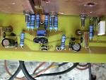
F5 turbo I got there first
24 V traffos Ceck
Loads more caps Ceck
Cascode Ceck
parallel Imput Jfets Ceck
Space on the board for 2 source resistors Cek
No current limiter transistors Cek (from day one)
P3 oh Crumbs

Diodes on sources not so far
Attachments
Now it's getting hotter...
Sorry not like me to be like this and spoil party for everyone...
But I feel funnier than usual and so I am going to start a big one....
F5 turbo I got there first
 Well to steer things a bit MY left diodes must be overheating again.
Somebody meke me feel realy silly for 5 seconds or such when he told me that I could not cascode the F5 unless it was balanced.
Even beter this memeber (can i use member as in member of our comunity or sin binn?)
did not heve eard or built an F5.
You Know who you are!
Impunity may be one thing, - the supply situation of FQA19N's and 12P's may solve that easily - or are the other versions of FQAs concidered direct replacements ( max current concidered.. ) ?
I have FQP19N20 the TO220 version of the FQA
Current is nearer to the counterparts
They have been running since August and no problem so far.
They are still avvaliable evveriwhere.
how do you calculate the power in class A?
For example, in F5T V1, with +-32V rails, and 1.0 amp per device, with two pairs per channel, giving a bias of 4 amps per channel.
P = I^2 x R = 4^2 x 8 = 128W peak.
From the original F5 manual, average would be 64W and this would be the power in class A. Correct?
For example, in F5T V1, with +-32V rails, and 1.0 amp per device, with two pairs per channel, giving a bias of 4 amps per channel.
P = I^2 x R = 4^2 x 8 = 128W peak.
From the original F5 manual, average would be 64W and this would be the power in class A. Correct?
Further to the discussion in post #7 :
http://www.diyaudio.com/forums/pass-labs/206240-f5-turbo-posted.html#post2896992
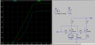
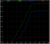
We have done some simple Spice simulations to compare the two output arrangements.
The attached figure shows in green the Current (Id) vs Drive Voltage (Vg) characteristics of the 2SK1530+0R5//MUR2020 in grey-blue, vs 2SK3497+0R22 in green.
The sharp knee point circled in red is that at which the conduction of the diode becomes prominant.
The simulation is not 100% reality, as the models are room temperature based and probably somewhat simplified. But it does show clearly how the characteristics of the 2SK3497+0R22 being dominated by the resistor, due to the much higher Yfs than the 2SK1530 at the same bias.
The upper knee point at Vg~6V is due to the MOSFET running out of Vds headroom (largely due to the 2R load resistor I added to the top rail).
Patrick
http://www.diyaudio.com/forums/pass-labs/206240-f5-turbo-posted.html#post2896992
We have done some simple Spice simulations to compare the two output arrangements.
The attached figure shows in green the Current (Id) vs Drive Voltage (Vg) characteristics of the 2SK1530+0R5//MUR2020 in grey-blue, vs 2SK3497+0R22 in green.
The sharp knee point circled in red is that at which the conduction of the diode becomes prominant.
The simulation is not 100% reality, as the models are room temperature based and probably somewhat simplified. But it does show clearly how the characteristics of the 2SK3497+0R22 being dominated by the resistor, due to the much higher Yfs than the 2SK1530 at the same bias.
The upper knee point at Vg~6V is due to the MOSFET running out of Vds headroom (largely due to the 2R load resistor I added to the top rail).
Patrick
Attachments
Last edited:
:
F5 turbo I got there first
Not shure.
http://www.diyaudio.com/forums/pass-labs/121228-f5-power-amplifier-959.html#post2415822
congrats! Show us more pics... and please tell us how it sounds.
Tanks but all the merit goes to Papa and quite a few members here
To name just 2 mighty Zen and Jaco (he was the one to mention duble J on the inputs.
I am quite proud of the 5mm bycolor leds on a 1 mm hole and luky to have chosen the big sinks (I was going to build somethink else)
But then (see how much power you reealy need tread by Pano).
Loads of pictures on 6L6 how to build an F5 and on my MY F5 tread.
Iwas going to post a bit more about sound as I got stuck with decent Pre so now that is in hand and a load more there will be up soon.
V3 maybe not I want F6 now
Start with maching your dudas ....
Still it sound fantastic much much beter that sometink I would haw bought in the shoop...
how do you calculate the power in class A?
For example, in F5T V1, with +-32V rails, and 1.0 amp per device, with two pairs per channel, giving a bias of 4 amps per channel.
P = I^2 x R = 4^2 x 8 = 128W peak.
From the original F5 manual, average would be 64W and this would be the power in class A. Correct?
The way I understand it (and I'm far far from an expert), is the output FETs can swing about 28V after losses. So I = V/R = 28V/8Ohm = 3.5A. If you bias the channel to 4A you will stay in Class A at 8ohms at max output.
P = I^2 x R = 3.5A^2 x 8Ohms = 98W peak or 49W RMS
Like I said, I'm definitely no expert so someone else correct me if I messed this up.
Thanks so much for this.
Anyone have a source for the semiconductors? ...
For the JFETS, eBay seller "alweit" has well-matched pairs. Highly reccommended seller!
eBay - See alweit's JFETS here
Correct, no shure cartridge ....
.- Status
- This old topic is closed. If you want to reopen this topic, contact a moderator using the "Report Post" button.
- Home
- Amplifiers
- Pass Labs
- F5 Turbo is posted