Ok. Got on a roll tonight and got some more stuff done.
Top view. Drilled and tapped holes for the PSU PCB. Also soldered all the wires to it. Not sure how the final assembly will go yet...
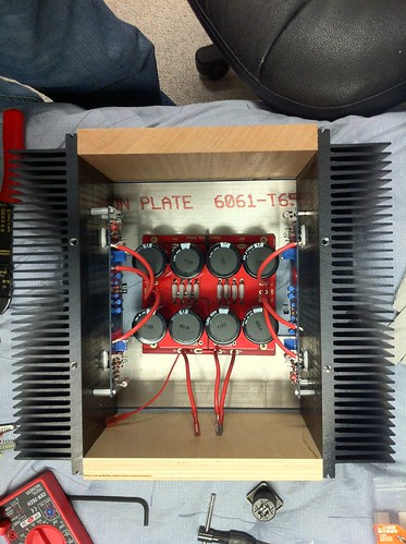
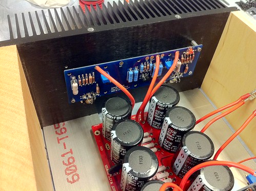
Mock up of where the power wires will go.

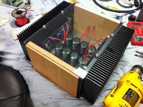
With the plexiglass top in place.
So sleepy. Tomorrow, hoping to get the rear panel drilled for the speakon jack, rcas, and maybe the speaker posts if I can find some. Could even get to testing the boards! Kinda scared though. Need to build a bulb tester first I guess.
Top view. Drilled and tapped holes for the PSU PCB. Also soldered all the wires to it. Not sure how the final assembly will go yet...
Mock up of where the power wires will go.
With the plexiglass top in place.
So sleepy. Tomorrow, hoping to get the rear panel drilled for the speakon jack, rcas, and maybe the speaker posts if I can find some. Could even get to testing the boards! Kinda scared though. Need to build a bulb tester first I guess.
have you tested the transformer wiring up yet?
Follow that by adding on the PSU.
Then test one amplifier. Then test the other amplifier.
Second to final test the whole assembly before you start putting it in a box.
Finally assemble the boxed version exactly replicating the electrical wiring that you know works silently on the bench.
Follow that by adding on the PSU.
Then test one amplifier. Then test the other amplifier.
Second to final test the whole assembly before you start putting it in a box.
Finally assemble the boxed version exactly replicating the electrical wiring that you know works silently on the bench.
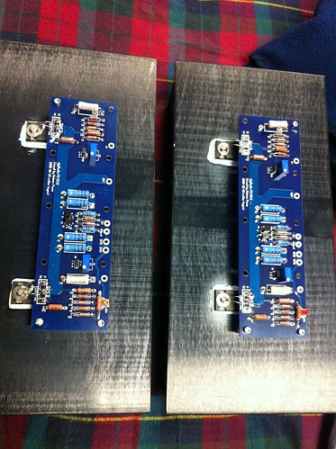
Holes tapped, boards attached.
Also bought some glossy letters that will go on the front. They're 2" tall. A little fancy for my usual tastes, but I thought I would try to go a little outside my typical tendencies.
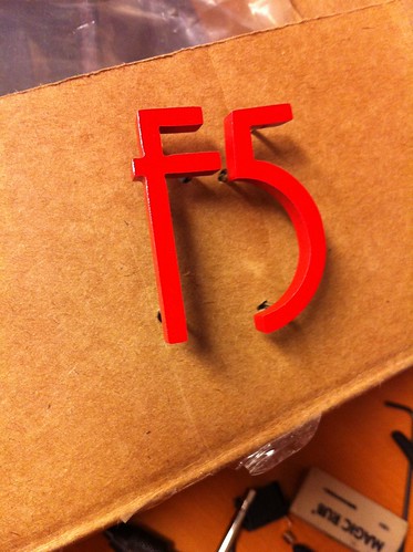
Next... fabricate the other four sides of the enclosure.
Where did you get those letters! I want some for my F2

have you tested the transformer wiring up yet?
Follow that by adding on the PSU.
Then test one amplifier. Then test the other amplifier.
Second to final test the whole assembly before you start putting it in a box.
Finally assemble the boxed version exactly replicating the electrical wiring that you know works silently on the bench.
That is the best advice that has appeared in this thread.
Test just the PSU, then, with no amp boards attached connect the PSU in your heatsink chassis and make sure that is doing what you expect. Then attach the amp boards one at a time.
Sign Letters / Wooden Letters / Plastic Letters / Metal Letters
I got the powder coated aluminum ones:
I got the powder coated aluminum ones:
Where did you get those letters! I want some for my F2
Thanks for the tip. That was going to be my methodology pretty much. As a matter of fact, the transformer wiring is good through the pair of caps in the PSU box already. I've read the amp board setup process a couple times so hopefully that goes fairly well.
One question for this set of boards. I think I know this... but can someone confirm where I measure to make sure the trim pots are installed correctly (i.e., in the correct orientation)? Or more importantly, make sure that their initial setting is where it's supposed to be at zero. (Can you tell I'm paranoid about this one?)
Also, how do folks connect the PSU wires to the boards? Should I just solder one in and then test and then solder the other one in? That doesn't let me test independently so I was thinking about using some kind of connector.
have you tested the transformer wiring up yet?
Follow that by adding on the PSU.
Then test one amplifier. Then test the other amplifier.
Second to final test the whole assembly before you start putting it in a box.
Finally assemble the boxed version exactly replicating the electrical wiring that you know works silently on the bench.
Thanks for the tip. That was going to be my methodology pretty much. As a matter of fact, the transformer wiring is good through the pair of caps in the PSU box already. I've read the amp board setup process a couple times so hopefully that goes fairly well.
One question for this set of boards. I think I know this... but can someone confirm where I measure to make sure the trim pots are installed correctly (i.e., in the correct orientation)? Or more importantly, make sure that their initial setting is where it's supposed to be at zero. (Can you tell I'm paranoid about this one?)
Also, how do folks connect the PSU wires to the boards? Should I just solder one in and then test and then solder the other one in? That doesn't let me test independently so I was thinking about using some kind of connector.
zero your pots by measuring ohms across R3 & 4
cheers Woody
They are genuine Bourns pots, yes? Start with them fully CCW
Yes, Bourns. The confusion is whether I installed backwards or not.
Weird. When I measure across the resistors, the values slowly rise till I get an open circuit. Is that a problem with my cheapo DMM?
They are genuine Bourns pots, yes? Start with them fully CCW
hmmmm doesn't the direction depend on which way you put them in ?
Well, it only sorta depends on which way they were put in - the PCB does 'key' the pot in a certain direction. And CCW is CCW regardless of which way you look at it, or which way the pot is oriented.
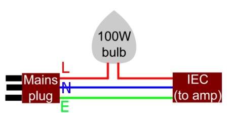
Anyway, as Andrew said, if the light bulb rig glows really bright they are all the way the wrong way, or you have other problems.
You do have a Lightbulb rig, right? If you don't, you need to make a run to the local hardware store before you do anything else.
Anyway, as Andrew said, if the light bulb rig glows really bright they are all the way the wrong way, or you have other problems.
You do have a Lightbulb rig, right? If you don't, you need to make a run to the local hardware store before you do anything else.
Well, it only sorta depends on which way they were put in - the PCB does 'key' the pot in a certain direction. And CCW is CCW regardless of which way you look at it, or which way the pot is oriented.
not trying to make an issue out of this , but the pot can go in either way . the wiper ,pin 2 ,center pin will always go towards pin number 1 ccw and pin 3 cw . if you have the pot in one way ccw will decrease resistance . turn the pot 180 deg and ccw will increase resistance .
that's why you ALWAYS need to check with a meter . NOT by just turning it all the way any one way .
cheers Woody
Exactly. Which brings us back to the issue of why my resistance number increases with time? Takes about 10 seconds till it reads open. If I read voltage for a little while it sort of resets. Weird.
Also, any comments on the psu PCB connection would be appreciated.
Thanks!
Maybe the thermistors (TH1, TH2) are warming up and affecting the R?Exactly. Which brings us back to the issue of why my resistance number increases with time? Takes about 10 seconds till it reads open. If I read voltage for a little while it sort of resets. Weird.
Maybe the thermistors (TH1, TH2) are warming up and affecting the R?
Doubt it. They would warm up from what the DMM puts in? Also, shouldnt it just read what's going across the pot?
Unfortunately, far from complete!
But you're right, it should measure everything in the completed circuit on the board. But not powered up as of yet.
But you're right, it should measure everything in the completed circuit on the board. But not powered up as of yet.
My suggestion was based on your latest pics which appears to be a completed F5, so measuring across the pot will read everything that's across the meter probes -- which is the entire circuit...
- Status
- This old topic is closed. If you want to reopen this topic, contact a moderator using the "Report Post" button.
- Home
- Amplifiers
- Pass Labs
- oneplustwo F5 build thread