Made some progress today and just wanted to double check a couple things with you all.
(CAPS ARE BACKWARDS IN PHOTOS)
Connections from transformer to rectifiers to caps:
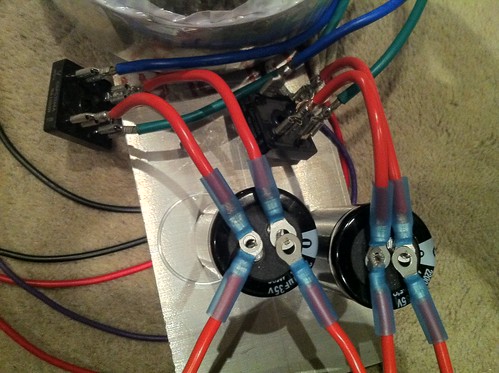
Minus/Ground/Plus from left to right along the bottom:
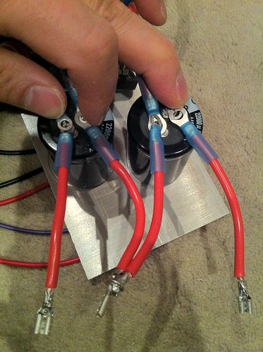
These connect to the umbilical jack (in my case, a neutrik 4-pole).
I'm going to route the primary wires below the aluminum plate for the terminal blocks, thermistors, and such. The IEC will be located below the plate as well.
Hope that makes sense! Please let me know if anything isn't clear and if everything is ok otherwise!
Thanks!
- From the transformer, blues and greens (Antek) go to the same tabs on the rectifiers.
- Then the + output of the rectifiers go to the + tabs of the caps (with the other tabs going to the minus tabs of the caps of course).
- Then one + cap tab connects to the umbilical tab as the +, and one - cap tab connects to the umbilical tab as the -.
- The remaining + and - are connected together and go to the umbilical as the ground.
- That same ground is connected to the chassis and earth ground via a thermistor.
- I also use the terminal blocks and thermistors and C9 in this enclosure (not the amp enclosure)
(CAPS ARE BACKWARDS IN PHOTOS)
Connections from transformer to rectifiers to caps:
Minus/Ground/Plus from left to right along the bottom:
These connect to the umbilical jack (in my case, a neutrik 4-pole).
I'm going to route the primary wires below the aluminum plate for the terminal blocks, thermistors, and such. The IEC will be located below the plate as well.
Hope that makes sense! Please let me know if anything isn't clear and if everything is ok otherwise!
Thanks!
Last edited:
I would start by connecting the safety earth to the psu chassis and running a wire attached to that point, through the umbillical and then on to the amp chassis. The audio ground should attach to the safety earth in the amp chassis through the CL-60.
Float all your connections/connectors/jacks off the chassis except for the safety earth.
Float all your connections/connectors/jacks off the chassis except for the safety earth.
Even with an oscilloscope?There will be ripple.
I know that it is so low that I cannot measure it.
My Fluke 73 doesn't stay steady under 10mVAC ripple either. But I would have thought an oscope would have no problem?Certainly not with my oscilloscope.
My Multimeters are much more sensitive and they can't measure the ripple when it's low.
Hum signal down around 0.3mVpp will be in noise.
That equates to roughly 0.1mVac of 50/60Hz hum.
I can't see hum at that level on my 2mV/div scope.
At double that level I would just be able to see the slow moving waveform in the picturewhole noise, but the signal is too low for the scope to lock on and allow me to see the hum signal.
That equates to roughly 0.1mVac of 50/60Hz hum.
I can't see hum at that level on my 2mV/div scope.
At double that level I would just be able to see the slow moving waveform in the picturewhole noise, but the signal is too low for the scope to lock on and allow me to see the hum signal.
Made some more progress and will have pics ths weekend. In the meantime, any recos on a cheap but good computer fan? Thinking about building a "fan base" as someone had suggested earlier and wanted a reco on a quiet fan. This one seems good: http://www.amazon.com/Cooler-Master-Computer-Cooling-R4-LUS-07AR-GP/dp/B002LE8BJA
Not cheap, but hoping the large size means I can run it slowly and keep it quiet but still move a good amount of air. Maybe get a pot to control speed.
Thoughts?
Not cheap, but hoping the large size means I can run it slowly and keep it quiet but still move a good amount of air. Maybe get a pot to control speed.
Thoughts?
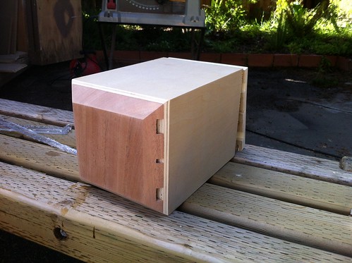
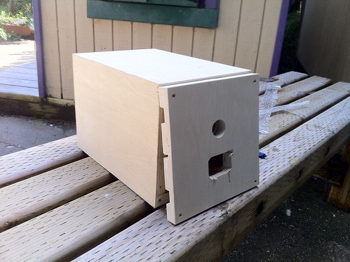
enclosure progress
Here's the PSU enclosure. It's a basic square cross section box with mitered construction:
The front beveled panel is some left over African Mahogany from my Zaph SR-71 build:
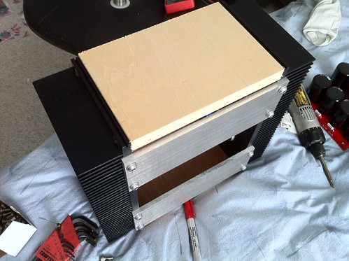
Here, you can better see the top and bottom vent holes which I planned to match the middle one which is where the 1/4" aluminum plate that everything is mounted to will sit. Matching slots on the rear.
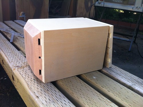
And here's the rear which will be screwed in place:
The IEC hole is a bit shoddy which I'm not happy about, but oh well.
Carried through the theme to the amp with African mahogany on the front and plywood on the rear again:
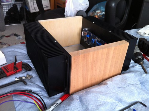
View of the bottom and front:
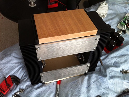
View of the bottom and rear:
I cut a piece of plexiglass for the top and it will screw in place on top of the heat sink.
Here's the PSU enclosure. It's a basic square cross section box with mitered construction:
The front beveled panel is some left over African Mahogany from my Zaph SR-71 build:
Here, you can better see the top and bottom vent holes which I planned to match the middle one which is where the 1/4" aluminum plate that everything is mounted to will sit. Matching slots on the rear.
And here's the rear which will be screwed in place:
The IEC hole is a bit shoddy which I'm not happy about, but oh well.
Carried through the theme to the amp with African mahogany on the front and plywood on the rear again:
View of the bottom and front:
View of the bottom and rear:
I cut a piece of plexiglass for the top and it will screw in place on top of the heat sink.
Last edited:
That looks really cool...
wow...nice. Hey 6L6...your writeup on the F5 is fantastic btw. Unfortunately for you...sometime in the near future, you're going to be my go to guy when I start my build. At this point...I have no idea what im doing...so good luck
- Status
- This old topic is closed. If you want to reopen this topic, contact a moderator using the "Report Post" button.
- Home
- Amplifiers
- Pass Labs
- oneplustwo F5 build thread