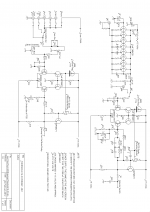
My Threshold SL10 Mk 1 was finally taken out of the cupboard to fit new caps
and replace the J505 constant current diodes and 2N172 Mosfets as the pins were showing signs of corrosion. This was an ideal time to trace out the circuit which is presented here as there are notable differences to the SL 10 circuits previously presented in DiyAudio. The MK1 designation is my own concoction to identify the different circuits in the SL10 stable.
Bill Sadler
Attachments

What is the gain of the MC-pre section?
I can't find any published specs for the SL10's preliminary gain section or my NS10's M1 module, nearly the same circuit, but here's a hint from contemporary Threshold Corp literature on the M1:
"...seven transistors per channel [eight in the SL10], direct coupled to the input, are operated without feedback to form an active impedance matching circuit where the gain factor is the ratio of the sum of the cartridge and input impedance to the M1 output impedance".
p.s. I had the luck to compare a friends SL10 with my NS10 - the SL10 has the clear edge in gain and low end control with low output MCs
pps - William -nice circuit,
") - isn't there a 22R with another 22R switched in parallel on the input to the MC input?
- isn't there a 22R with another 22R switched in parallel on the input to the MC input?-Mal
What is the gain of the MC-pre section?
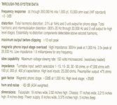
According to the SL10 brochure, the MM section has 33db gain at 1khz.
The MC section adds another 20db gain.
---Gary
Attachments
Last edited:
I think the 20dBs are referred to the line stage....
That's correct.
The MC gain depends which MC cartridge you are using.
How much gain is possible? Here's my example:
My MC cartridge's output is only 0.2 mV, so the input impedance selected on the preliminary phono gain (MC) stage is the lowest setting on the SL10: 1 through 15 ohms (highest gain possible).
The MM RIAA phono gain stage adds +33dB. To feed the high level stage (+20 dB gain) with 1 volt requires +74dB total gain, not quite a volt in my setup, so the SL10's MC section gain is about +40dB.
-Mal
Attachments
Threshold SL10 Mk1
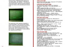
Malatron you are correct, I have the original operating manual which specifies the gain of the MM stage as 33 dBs and a gain of 20 for the line stage, by the way this is over the top, way too much gain, I have added so much resistance in series with the Volume control. This has affected the sound so I am going to have to find another way of killing gain, I can use the MM stage as a MC stage with just impedance adjustments. I am of the opinion that the circuit I published is all washed out and not very clear, I have redone the circuit to improve the resolution but must find a way of replacing the circuit published.
William
Threshold SL10 Mk1
Zen Mod Thanks for that, I have been playing with
both the RIAA stage and the Line Stage in LTSpice and have various options.
Leave the RIAA stage as is for the moment (I have redesigned the RIAA
feedback components) and then use a 10K resistor in place of the 1K5 in the
feedback leg of the Line Stage mounted proud of the PCB to enable different
resistor values to be easily added in parallel to avoid repeatably messing
with the PCB. A 5K resistor (10K || 10K) will then give 8 dB gain with the
gain switch open and 12 dB gain with the gain switch closed. I also want to
avoid fiddling with the PCB too much as it doesn't take kindly to removing
components with thru the hole soldering.
ps I have tried this, much better and I am in the ball park of were I want
to be.
As confucius says "it is not the work stupid but the decisions decisions"
- Status
- This old topic is closed. If you want to reopen this topic, contact a moderator using the "Report Post" button.
- Home
- Amplifiers
- Pass Labs
- Threshold SL10 MK1