OK, so after some pushing by a friend who wanted a Pass B1 for less than the $1k retail price, I agreed to build him one. I've read through all the build threads, the reviews, etc. to get acquainted with the project. Intrigued, I decided to build myself one as well to go with a little 2050 Sure amp I have from Parts-Express and turn that into a small integrated amp for the garage or nursery.
While I'm no EE, I've been involved with basic electronics, mainly audio (Pro, Car, and Home), for my whole life and can get around a bit more than your average joe.
That said, I put together the BOM, starting with the board from Pass DIY with matching JFETs, and the rest from Digikey and Parts-Express. As at least a test power supply, I had a few Dell Laptop bricks laying around that are 18.5V DC @ 3.3Amps. Plenty for the B1 and enough to test the 2050 setup for functioning.
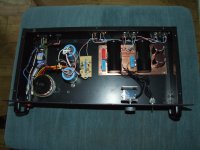
I assembled mine last night as a single input version and ran the outputs into the 2050 input, hooked up my iphone as a test signal (vs. pulling out the SACD player from the rack), wired some spare B&W bookshelf speakers, and gave power to the setup. The power supply when hooked just to the amp works fine, but as soon as hook up the B1 (alone, or in parallel with the amp), the LED on the B1 comes on faintly for short moment then the LED on the Power Supply goes out and nothing works.
It's like something is shorted on the B1, but I can't figure it out.
You'll see for the inputs I simply mated a ground with input that feeds to the Pot, though I could have wired them to the Pot leads corresponding with input & ground.
Is something obviously wrong here?
Is there any issue with the B1 sharing power with the amp?
Anything I should triple check?
While I'm no EE, I've been involved with basic electronics, mainly audio (Pro, Car, and Home), for my whole life and can get around a bit more than your average joe.
That said, I put together the BOM, starting with the board from Pass DIY with matching JFETs, and the rest from Digikey and Parts-Express. As at least a test power supply, I had a few Dell Laptop bricks laying around that are 18.5V DC @ 3.3Amps. Plenty for the B1 and enough to test the 2050 setup for functioning.
I assembled mine last night as a single input version and ran the outputs into the 2050 input, hooked up my iphone as a test signal (vs. pulling out the SACD player from the rack), wired some spare B&W bookshelf speakers, and gave power to the setup. The power supply when hooked just to the amp works fine, but as soon as hook up the B1 (alone, or in parallel with the amp), the LED on the B1 comes on faintly for short moment then the LED on the Power Supply goes out and nothing works.
It's like something is shorted on the B1, but I can't figure it out.
You'll see for the inputs I simply mated a ground with input that feeds to the Pot, though I could have wired them to the Pot leads corresponding with input & ground.
Is something obviously wrong here?
Is there any issue with the B1 sharing power with the amp?
Anything I should triple check?
An externally hosted image should be here but it was not working when we last tested it.
The B1 is about as simple as simple gets.
FIRST and FOREMOST, are you absolutely certain that all the component values are correct and that everything has been orientated correctly ?
SECOND, are you absolutely certain that there are no shorts on the PCB ?
The ONLY route for significant current to pass is around R1, C1.
If R1 is touching the PCB, there is a potential current path through R1 to the Ground PLANE. Try lifting R1 ever so slightly clear of the PCB.
This might now sound stupid, but, is C1 a reputable cap ? Is it the right way round ? Is it faulty ? Do you have a poor joint at R1 ?
Is the PSU still outputting 18V even though the B1 is not working ?
Last edited:
Using a meter measure the resistance between Vcc (+ve) and the Cathode of D1.
It should be 1 Ohm.
Then try measuring between Vcc (+ve) and 0V. This should start at a very low resistance and gradually increase as C1 charges using the meter battery.
If these are OK try another PSU with the B1. 2 x PP3 batteries in series for example.
MN1604 6LR61 for those in foreign parts.
It should be 1 Ohm.
Then try measuring between Vcc (+ve) and 0V. This should start at a very low resistance and gradually increase as C1 charges using the meter battery.
If these are OK try another PSU with the B1. 2 x PP3 batteries in series for example.
MN1604 6LR61 for those in foreign parts.
Last edited:
What Andrew T and I are both trying to ascertain is wether this is a B1 or a PSU issue.
It's possible that the enormous C1 on the B1 is affecting the computer PSU. Post #4 will iron this out.
If it's late at night and you are short of 9V batteries. Just remove C1. You might get a bit of hum but it will prove where the problem lies.
I had no problems with mine.
It's possible that the enormous C1 on the B1 is affecting the computer PSU. Post #4 will iron this out.
If it's late at night and you are short of 9V batteries. Just remove C1. You might get a bit of hum but it will prove where the problem lies.
I had no problems with mine.
Attachments
Last edited:
Don't worry about the position of D1 on my homebrew PCB. Yours is correct - so is mine. The two PCBS are slightly different.
My C101 and C201 are obviously very different. I used Obbligato PIOs which take up some serious space.
I also used Siemens 1.0uF MKP 400V for C100 and C200.
The caps wouldn't cause the issues that you have though.
It is possible that you've got a FET conducting when it shouldn't be.
I'm suspecting that the PSU doesn't like the huge capacitive load.
Removing C1, will iron that out. Or you could try putting a 100R resistor in series with Vcc.
Last edited:
i WOULD TRY IT WITH A PAIR OF 9 VOLT BATTERIES. sOUNDS LIKE SOMETHING WITH THE POWER SU[PPLY. DID YOU MEASURE ITS OUTPUT VOLTAGE? i'M USING SOMEKIND OF A LAPTOP POWER SUPPLY, RARELY DO THEY HAVE A STANDARD SIZED PLUG, AND THERE IS USUALLY A THIRD WIRE WHICH HAS SOMETHING TO DO WITH CHARGING THE LAPTOPS BATTERY. dID YOU CUT OFF THE EXISTING PLUG AND REPLACE IT? i HAD A PLUG AT FIRST THAT SHORTED, REPLACED IT WITH A BETTER ONE.
sTUPID CAPS LOCK!
rUSSELLC
sTUPID CAPS LOCK!
rUSSELLC
There you go. Another member suggesting that the PSU is causing the problem.
Well, the B-1 is so simple that the power supply is all that's left. I guess you could mis orient an electrolytic cap, or put in a fet backwards, but when he said the LED came on then went off, I figured power supply. On the other hand, my laptop PS worked fine.
Russellc
I would suspect that, IF one or more FETs is faulty or incorrectly orientated, then IF the PSU is trying to output 3.5A at 18V (80W) something would be smoking or at least getting VERY VERY HOT..
I go back to try a battery. Once we know whether it is the PSU or the B1 we can offer some suggestions.
I go back to try a battery. Once we know whether it is the PSU or the B1 we can offer some suggestions.
Have a look at http://www.diyaudio.com/forums/pass...-your-diy-pass-amplifier-107.html#post2872065 POST 1063 to see one in full swing.
It really annoys me when a posting goes DRY.
The original poster should post that he has resolved the problem - so that those are helping him/her are thanked. OR to say that they have given up.
JUNG4G please post a status report.
I apologize that I have a job and family to attend to far more often than my projects... twas not my intent to offend and did not expect a response so quickly.
I greatly appreciate the input and haven't had a chance to test further since reading the responses moments ago and likely will not until tomorrow.
The suspicions around C1 triggering some fault in the PSU are also my thoughts.
In response the 3rd pin the Laptop PSU, which I also believe is part of a feedback circuit related to charging laptop batteries, I simple removed the plug and hard wired the supply and in turn left that 3rd conductor open.
The supply measures the intended 18.5v with no load, and 0v once hooked up to the B1 as the supply's LED turns off to indicate that it is no longer running. Unplugging at the wall and re-plugging it turns the supply back on, but not for long enough to register the output voltage.
I also like the idea of putting a 100ohm or similar resistor between the supply and VCC, quite simply, that should simply allow C1 to charge more slowly as to not trigger a protection circuit on the PSU, correct?
I'll round up some 9Vs to test via battery power and run through the other suggestions as well and then report back.
Try the 9v batteries, they are always a good test for this circuit.
Do you perhaps have an 18v linear wall wart laying around? It's not all that uncommon, maybe a wireless phone or something like that.
Also, if you have a different capacitor, say 1000uf or thereabouts, you could use it in place of C1, so the starting load is lower. The 15,000uf cap might just be too big for your PSU, I wouldn't be surprised if it's shutting down due to current limiting. The R in series is also a good idea to slow the charging down.
Less than 48 hours and you can't stand it anymore? Although you are quite entitled to your opinion about being annoyed, you probably should keep that to yourself. This is a hobby website after all! We're here to help, have fun, and generally 'hang out' with like-minded individuals.
Do you perhaps have an 18v linear wall wart laying around? It's not all that uncommon, maybe a wireless phone or something like that.
Also, if you have a different capacitor, say 1000uf or thereabouts, you could use it in place of C1, so the starting load is lower. The 15,000uf cap might just be too big for your PSU, I wouldn't be surprised if it's shutting down due to current limiting. The R in series is also a good idea to slow the charging down.
It really annoys me when a posting goes DRY.
Less than 48 hours and you can't stand it anymore? Although you are quite entitled to your opinion about being annoyed, you probably should keep that to yourself. This is a hobby website after all!
We're here to help, have fun, and generally 'hang out' with like-minded individuals.
Last edited:
It only took one simple test to figure this out and C1 was definitely the cause.
It's not a bad cap, just a big one and as suspected by more than one, it was simply causing the PSU to "see" a short and shut down. I simply tested that with by throwing the smallest resistor I had within reach inline with VCC, in this case a 221ohm which simply slowed the charge enough to get the B1 up to speed without issue.
As a further test I disconnected during playback and let it run off the C1 reserves for a moment (no problems there) and then connected VCC direct to the PSU, bypassing the 221ohm resistor. It kept playing just fine and the PSU didn't complain.
For one last test, I then disconnected the PSU again and let it play out the reserve in C1, about 15-20 seconds until the volume started to fade at which point I connected VCC direct to the PSU again. The depleted C1 was enough to trigger the original fault for the PSU and it shut off.
Not only was I very happy to have the B1 work with such a simple tweak, but I was blown away with the sound. I can't wait to get this thing in line with my full system versus this test rig.
One question, what's the best way to set this system up permanently with my current PSU for the B1? Should I just up the value of R1? Any drawbacks on doing that?
It only took one simple test to figure this out and C1 was definitely the cause.
It's not a bad cap, just a big one and as suspected by more than one, it was simply causing the PSU to "see" a short and shut down. I simply tested that with by throwing the smallest resistor I had within reach inline with VCC, in this case a 221ohm which simply slowed the charge enough to get the B1 up to speed without issue.
As a further test I disconnected during playback and let it run off the C1 reserves for a moment (no problems there) and then connected VCC direct to the PSU, bypassing the 221ohm resistor. It kept playing just fine and the PSU didn't complain.
For one last test, I then disconnected the PSU again and let it play out the reserve in C1, about 15-20 seconds until the volume started to fade at which point I connected VCC direct to the PSU again. The depleted C1 was enough to trigger the original fault for the PSU and it shut off.
Not only was I very happy to have the B1 work with such a simple tweak, but I was blown away with the sound. I can't wait to get this thing in line with my full system versus this test rig.
One question, what's the best way to set this system up permanently with my current PSU for the B1? Should I just up the value of R1? Any drawbacks on doing that?
Congrats on finding the fault, glad you like the sound of the circuit. Very simple, single ended, class A, and no feedback. As to setup, I'm at a loss why the power supply shut off, lots of builders have used laptop type power supplies withut issue. I bought one off ebay for some kind of a dell lap top or notebook with the correct voltage, and its always worked fine. Once powered up, I just leave it on, s maybe you could just do that, since it wrked fine once underway. I dont know if there is a problem with leaving the resistor in there all the time, but I wouldnt think so as long as it dosent get too hot or anything.
Russellc
One question, what's the best way to set this system up permanently with my current PSU for the B1? Should I just up the value of R1? Any drawbacks on doing that?
Add a simple LM317-based (or a conventional 2-transistor) CSS in between the B1 and the power supply.
The datasheet for the 317 shows the typical way to do it.
One LM317 and one resistor is all it takes. With a 10 ohm resistor this CSS will limit the current to ~125 mA.
I found that the B1 works at its best with a low impedance power supply.
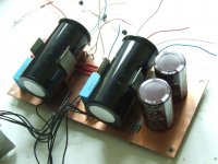
To that end you might prefer the sound with a standard Transformer/Bridge/CRC supply.
You only need 22V at 20mA so a tiny 15V transformer will do the job.
I used a 30VA toroid / 1A Brdge / 4700uF / 2R2 / 4700uF but that's because that is what I had lying around.
The little board in the centre is an LM317 regulator, simply because my transformer was 18V and I wanted to reduce the supply to 22V.
With a 15V transformer it's not necessary.
Attachments
Last edited:
- Status
- This old topic is closed. If you want to reopen this topic, contact a moderator using the "Report Post" button.
- Home
- Amplifiers
- Pass Labs
- Pass B1 DIY - Need Help