I've bought two of these off E-Bay, excellent quality and a really good price. Obviously they are not the same width but they match each other.
215*70*228mm Aluminum enclosure DAC case amplifier chassis DIY BOX HIFI house | eBay
215*70*228mm Aluminum enclosure DAC case amplifier chassis DIY BOX HIFI house | eBay
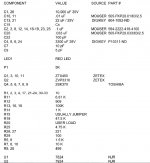
Has anyone got a copy of the BOM for this project ?
https://www.passdiy.com/project/preamplifiers/pearl-2
Towards the bottom of the article.
Does anyone know why the ZVP3310 is so prone to failure ?
My guess? ESD.
Hello,
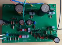
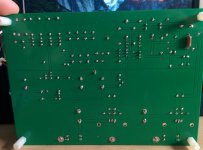
I've been busy an unable to sit down an get to work. I finally did that and i've got a couple of pictures of the board and I took voltage readings of all the Rs and Qs.
R1 Top:35.8 Bottom:35.5
R2 Top:35.8 Bottom:35.6
R3 Top:23.8 Bottom:23.5
R4 Top:23.8 Bottom:23.5
R5 Left:20.26 Right:23.58
R6 Top:20.46 Bottom:18.74
R7 Top:20.27 Bottom:0
R8 Top:19.60 Bottom:5.734
R9 Top:19.6 Bottom:5.067
R10 Top:5.727 Bottom:0
R11 Top:5.056 Bottom:5.049
R12 Top:5.049 Bottom:5.046
R13 Top:0 Bottom:0
R14 Top:0 B:0
R16 Top:23.27 Bottom:23.04
R17 Top:23.28 Bottom:23.28
R18 Top:0.015 Bottom:0
R19 Top:0 Bottom:0
R21 Top:0.075 Bottom:0
R22 Top:0.075 Bottom:0
R23 Top:0.075 Bottom:0
R24 Top:0.075 Bottom:0
R25 Top:-22.32 Bottom:0
R26 Top:-22.32 Bottom:-22.32
R27 Top:-22.33 Bottom:-22.32
R28 Top:-22.92 Bottom:-24.06
R29 Top:-22.87 Bottom:-24.06
R30 Left:-36.34 Right:-36.30
R31 Top:-24.15 Bottom:-24.06
R32 Left:-36.30 Right:-36.18
R33 Top:-24.15 Bottom:-24.06
Q1 Top:23.58 Middle:20.27 Bottom:19.60
Q2 Top:23.57 Middle:18.74 Bottom:23.27
Q3 Top:5.061 Middle:5.719 Bottom:5.021
Q4 Top:18.73 Middle:0 Bottom:0.365
Q5 Top:23.57 Middle:0 Bottom:0.365
Q6 Top:5.020 Middle:0 Bottom:0.075
Q7 Top:5.011 Middle:0 Bottom:0.075
Q8 Top:5.014 Middle:0 Bottom:0.075
Q9 Top:5.015 Middle:0 Bottom:0.075
If any more readings are required please let me know. Any help is greatly appreciated.
-Thanks
Attachments
https://www.passdiy.com/project/preamplifiers/pearl-2
Towards the bottom of the article.
My guess? ESD.
The bottom of the article is corrupted and only includes a few of the capacitors, repeated many times.
The bottom of the article is corrupted and only includes a few of the capacitors, repeated many times.
The pdf version seems fine:
https://www.passdiy.com/pdf/PEARL 2.pdf
Hi K&D,
do you know the original article by Wayne? You can find it here:
https://www.passdiy.com/project/preamplifiers/pearl-2
There's a BOM at the end of it. Let me attach a screenshot of it.
Happy DIYing!
Cheers
poli
do you know the original article by Wayne? You can find it here:
https://www.passdiy.com/project/preamplifiers/pearl-2
There's a BOM at the end of it. Let me attach a screenshot of it.
Happy DIYing!
Cheers
poli
Attachments
Please be patient with me as I am new to the turntable world.
My cartridge will be the Linn Arkiv.
According to the spec sheet the output of the cartridge is 150uV and the load needs to be >50R
Is that output at a particular frequency, I do appreciate that the RIAA response is far from a flat line, or can I take that as the figure to work out my necessary gain.
What does load >50R mean ? 47R, 10R it could be anything less than 50R.
Is it reasonable to expect the Pearl 2 to bring the MC output up to CD line level (2VRMS).
What does load >50R mean ?
It means "greater than" 50 ohms.
jeff
No it's a re-tipped second hand one.
Re-tipped by the UKs leading experts.
I haven't received my boards from PassDiy yet. I've got some component leads sockets that I could fit to the board if the tracks will support them, if not I'll arrange some way of altering the loading without repeated soldering.
Re-tipped by the UKs leading experts.
I haven't received my boards from PassDiy yet. I've got some component leads sockets that I could fit to the board if the tracks will support them, if not I'll arrange some way of altering the loading without repeated soldering.
Last edited:
Ok, so it's probably one of these: Linn Arkiv B phono cartridge | Stereophile.com
You'll notice that the output is listed as .4mV, not the .15mV that's on the vinylengine page. I don't think the lower output is correct.
jeff
You'll notice that the output is listed as .4mV, not the .15mV that's on the vinylengine page. I don't think the lower output is correct.
jeff
Resistor Power Rating
Reading the Pearl 2 article Wayne states that he used mainly Dale/Vishay RN55D series resistors.
These are rated at 0.125W 1/8W.
In a later BOM they were specified as 0.5W.
I've ordered the 0.125W resistors, are there any that really need to be a bit more robust?
Reading the Pearl 2 article Wayne states that he used mainly Dale/Vishay RN55D series resistors.
These are rated at 0.125W 1/8W.
In a later BOM they were specified as 0.5W.
I've ordered the 0.125W resistors, are there any that really need to be a bit more robust?
Reading the Pearl 2 article Wayne states that he used mainly Dale/Vishay RN55D series resistors.
These are rated at 0.125W 1/8W.
In a later BOM they were specified as 0.5W.
I've ordered the 0.125W resistors, are there any that really need to be a bit more robust?
Several threads have discussed this, the short story is, they are very conservatively rated. You should be fine. there are a few places where the Panasonic 3 watts are used if I remember correctly....A few resistors are best left out until final fire up...I forget which ones, it is somewhere in this thread, that allow fire up of everything including the regulators, for test purposes. Then installing them fires up the whole circuit, once proper voltages are seen to be present.
Russellc
There's no 3W in the Pearl 2. This was the only thread that I could find with the Pearl 2 in it.
You may be right. The ones I'm talking about are along the edge where the power comes in, maybe they were dale/vishay. I think they were 10 ohm, but its been a while.
There is another thread on the Pearl 2 by Wayne when it was first introduced. This thread is 6L6's build guide.
http://www.diyaudio.com/forums/pass-labs/156397-pearl-two.html
there are also a few others that talk about modifying the RIAA, Jack and some others.
Russellc
Hello,
I've been busy an unable to sit down an get to work. I finally did that and i've got a couple of pictures of the board and I took voltage readings of all the Rs and Qs.
R1 Top:35.8 Bottom:35.5
R2 Top:35.8 Bottom:35.6
R3 Top:23.8 Bottom:23.5
R4 Top:23.8 Bottom:23.5
R5 Left:20.26 Right:23.58
R6 Top:20.46 Bottom:18.74
R7 Top:20.27 Bottom:0
R8 Top:19.60 Bottom:5.734
R9 Top:19.6 Bottom:5.067
R10 Top:5.727 Bottom:0
R11 Top:5.056 Bottom:5.049
R12 Top:5.049 Bottom:5.046
R13 Top:0 Bottom:0
R14 Top:0 B:0
R16 Top:23.27 Bottom:23.04
R17 Top:23.28 Bottom:23.28
R18 Top:0.015 Bottom:0
R19 Top:0 Bottom:0
R21 Top:0.075 Bottom:0
R22 Top:0.075 Bottom:0
R23 Top:0.075 Bottom:0
R24 Top:0.075 Bottom:0
R25 Top:-22.32 Bottom:0
R26 Top:-22.32 Bottom:-22.32
R27 Top:-22.33 Bottom:-22.32
R28 Top:-22.92 Bottom:-24.06
R29 Top:-22.87 Bottom:-24.06
R30 Left:-36.34 Right:-36.30
R31 Top:-24.15 Bottom:-24.06
R32 Left:-36.30 Right:-36.18
R33 Top:-24.15 Bottom:-24.06
Q1 Top:23.58 Middle:20.27 Bottom:19.60
Q2 Top:23.57 Middle:18.74 Bottom:23.27
Q3 Top:5.061 Middle:5.719 Bottom:5.021
Q4 Top:18.73 Middle:0 Bottom:0.365
Q5 Top:23.57 Middle:0 Bottom:0.365
Q6 Top:5.020 Middle:0 Bottom:0.075
Q7 Top:5.011 Middle:0 Bottom:0.075
Q8 Top:5.014 Middle:0 Bottom:0.075
Q9 Top:5.015 Middle:0 Bottom:0.075
If any more readings are required please let me know. Any help is greatly appreciated.
-Thanks
Looks to me you forgot to put a jumper in the spot of R15. Check the first post of this thread. The jumper is mentioned there and can be seen on later pictures of the boards.
Last edited:
- Home
- Amplifiers
- Pass Labs
- Building a Pearl 2