If you are using a 1/2 amp fuse you're okay.
I had the same problem with mine due to my bone head mistake was inserting the DVM leads into my meter wrong. I thought the power supply +V was -V and visa versa. Once I sorted that out and replaced the fuse it has run flawlessly ever since!
I had the same problem with mine due to my bone head mistake was inserting the DVM leads into my meter wrong. I thought the power supply +V was -V and visa versa. Once I sorted that out and replaced the fuse it has run flawlessly ever since!
A 1/2 amp slow blow or fast? A fast wouldn’t be able to survive the inrush of those caps.
How can I tell? I just bought it from a local shop and I asked them to make sure it was slow-blow, but now that you mention this he might not have checked.

How's the wiring? I double-checked everything. I think the only mysteries for me was the switch and do ground the shield input on the board to chassis ground. All my solder joints looked good.
I just checked online with differences between fast and slow blow fuses and I received a slow-blow. In that case, it must be something that I wired in correctly.
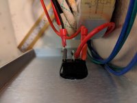
In my pictures, there is a photo of the switch. I wired the connection from the fuse to the plus tab and the red transformer connections to the "A" tab, could that be the problem?
In my pictures, there is a photo of the switch. I wired the connection from the fuse to the plus tab and the red transformer connections to the "A" tab, could that be the problem?
I just checked online with differences between fast and slow blow fuses and I received a slow-blow. In that case, it must be something that I wired in correctly.
In my pictures, there is a photo of the switch. I wired the connection from the fuse to the plus tab and the red transformer connections to the "A" tab, could that be the problem?
I miswired the secondaries to a purchased PSU board - 2 sets of secondaries onto one board. I effectively shorted the transformer output and it blew the fuse instantly. No damage to the transformer because the fuse did it's job. I got it right by trial and error in the end. Newbie learning curve stuff!
I miswired the secondaries to a purchased PSU board - 2 sets of secondaries onto one board. I effectively shorted the transformer output and it blew the fuse instantly. No damage to the transformer because the fuse did it's job. I got it right by trial and error in the end. Newbie learning curve stuff!
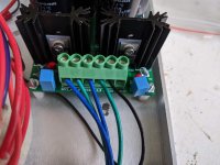
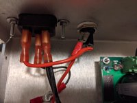
I have the secondaries 1a,2a,1b,2b all wired to the board in the photos I attached. I have the primaries (2 hots and 2 neutrals) tied to each other and then the hot to the switch and the neutral to the ac inlet. The shield wire of the transformer is also connected to the board where its says shield next to the secondary inputs.
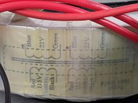
Here's the transformer that I am using: AS-0522 - 50VA 22V Transformer - AnTek Products Corp
Using a DMM and measuring the resistance of each secondary, you verified the correct green/blue pairs?
On a recent build, even after I checked the proper pairs with a DMM, I still managed to mix them up when wiring them into the PSU. The fuses kept blowing, blowing, and I spent two days trying to figure out what I did wrong with the PSU. Turns out I mismatched the pairs even though I checked already.
On a recent build, even after I checked the proper pairs with a DMM, I still managed to mix them up when wiring them into the PSU. The fuses kept blowing, blowing, and I spent two days trying to figure out what I did wrong with the PSU. Turns out I mismatched the pairs even though I checked already.
I have the secondaries 1a,2a,1b,2b all wired to the board in the photos I attached. I have the primaries (2 hots and 2 neutrals) tied to each other and then the hot to the switch and the neutral to the ac inlet. The shield wire of the transformer is also connected to the board where its says shield next to the secondary inputs.
Here's the transformer that I am using: AS-0522 - 50VA 22V Transformer - AnTek Products Corp
Disconnect the Pearl boards and try it again. If it blows, I assume you have the transformer wiring to the power supply wrong.
Using a DMM and measuring the resistance of each secondary, you verified the correct green/blue pairs?
On a recent build, even after I checked the proper pairs with a DMM, I still managed to mix them up when wiring them into the PSU. The fuses kept blowing, blowing, and I spent two days trying to figure out what I did wrong with the PSU. Turns out I mismatched the pairs even though I checked already.
I tracked down the appropriate secondaries with a multimeter. I tested all the connections and they seem ok. I powered it up and nothing happened but the fuse did not blow. I also changed where the leads of the hot connection of the ac inlet connect to the fuse, but I am not sure if that makes a difference? Are the secondaries arranged that blue is 1a and green 1b, or is that 1a and 1b are both blue and 2a and 2b are both green?
Here's some more photo attached. Any help would be great. Getting there.
Attachments
Last edited:
Do any of the pins of the XLR connect to chassis?
Blue is 1A green is 1B, those those wires need continuity to each other. The same with 2A and 2B.
Where is the black wire on the switch connected to?
None of the XLR pins connect to the chassis. The secondaries are wired as you wrote and I checked for continuity. I realized that is an older photo of the secondaries and where the black wire is connected at the shield input is now the purple shield wire from the transformer before it was a ground wire connected to the chassis.
Does the LED light up when it’s on?
No, it doesn't. I think the switch might be the problem. I tried it with the ground wire attached and not attached and it did not make a difference. I checked for continuity when it is on and if it is off with a meter and it performed as it should.
Ok, last annoying post of the night. I decided to fire it up after changing the ground connections. I still didn't get the led on the switch to light up but I checked the voltage off the xlr jack and I get - 31v off each side. Also, 6L6 do the LED's on the PCB need to light up or is it so low and just for voltage stability?
- Home
- Amplifiers
- Pass Labs
- Building a Pearl 2