Hi guys, waiting for the PCBs to arrive and will start to build shortly.
One question... Is a 30VA transformer sufficient for the Pearl?
The Pearl 2 doc calls for 2x22v which gives the right voltage after rectification.
The Pearl 2 doc calls for 2x22v which gives the right voltage after rectification.
The voltage is fine, it will be 2x22V, the power rating is 30VA, in the Pearl description a 50VA transformer is mentioned, but it is stated, that the current draw will be about 100ma, so approx. 30V DC *0,1A *2 = 6W?
The voltage is fine, it will be 2x22V, the power rating is 30VA, in the Pearl description a 50VA transformer is mentioned, but it is stated, that the current draw will be about 100ma, so approx. 30V DC *0,1A *2 = 6W?
Sorry I misread your post, I'm not sure if 30VA is enough.
30V DC *0,1A *2 = 6W?
Yep.
30VA is pretty much 30W for our purposes, so that transformer would be good for 5x the expected draw, and therefore should run quiet and cool.

Pass DIY Addict
Joined 2000
Paid Member
Yep, even going as low as 25VA works fine. I thought I posted this somewhere already, but I didn't see it in a quick look back through this thread.
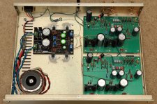
I recently rebuilt my Pearl II so the power supply is inside the box (got one shelf back in my equipment rack!). I used an Antek 25VA transformer and it works great. I'm not sure whether I used the 22v or 25v version of this transformer - my notes have a conflict in them. It was probably the 25v version to give the regulator 10v of headroom...
The transformer drives a Salas BiB v1.3 regulator that is set to draw ~200mA for each rail. The negative rail on the Pearl draws about 42mA for both boards, the positive rail draws about 84mA for both. The little 25VA toriod gets a little warm with the constant 400mA draw from the regulator, but certainly nothing to be concerned with.
I don't think this was necessary, but I added a small copper shield around the transformer to help corral the AC power wires and dressed it up a bit by replacing the metal front plate with a nice piece of figured walnut wood that I finished with tung oil. I added a front panel power switch and changed the grounding configuration a little since this image was made. I'll post an updated image with the wooden front panel tonight when I get home.
The result is nice and quiet with no AC or ground hum. In one channel, I get a very slight "popping" sound with my ear to the driver at full volume. I think Jim described as the popcorn sound inherent to the jFets.
Attachments
Thanks for the quick responce guys!
Looking great, was also thinking to implement the PSU in a common case and therefore use an R core transformer due to lower magnetic stray field.
Good to hear you had no hum problems. Btw I'm still having a slight hum on my F5 turbo, so I was a little bit sceptical about the phono stage.
Looking great, was also thinking to implement the PSU in a common case and therefore use an R core transformer due to lower magnetic stray field.
Good to hear you had no hum problems. Btw I'm still having a slight hum on my F5 turbo, so I was a little bit sceptical about the phono stage.
On my F5 hum comming from toroid transformer, if I rotate it, it gets worse. Right now the levels are acceptable and not hearable from listening position.Is the Hum PSU or ground loop?
Pass DIY Addict
Joined 2000
Paid Member
One thought from my recent explorations: if you have audible/mechanical/physical hum that comes from your transformer (get your ear close to the PSU with no speaker attached) that matches what you are hearing from your speakers, you might be able to solve this problem by adding an appropriate snubber network to the secondaries of your power transformer.
Have a look at this thread. Mark's quasimodo jig is easy to play with if you have a scope and silenced a humming transformer that I have.
Have a look at this thread. Mark's quasimodo jig is easy to play with if you have a scope and silenced a humming transformer that I have.
One thought from my recent explorations: if you have audible/mechanical/physical hum that comes from your transformer (get your ear close to the PSU with no speaker attached) that matches what you are hearing from your speakers, you might be able to solve this problem by adding an appropriate snubber network to the secondaries of your power transformer.
Have a look at this thread. Mark's quasimodo jig is easy to play with if you have a scope and silenced a humming transformer that I have.
The "snap" which Mark is referring to is that caused by the leakage inductance of the transformer and the junction capacitance of the rectifier diodes causing a tank circuit. It's usually resonates anywhere from a few hundred kHz to several MHz.
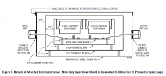
Best thing you can do to avoid the field from a trafo interfering with the Pearl is to use separate housings and an umbilical. Better yet, if you can find a small rectangular "tin" box, house the preamplifier section therein.
I am afraid that the way the ground pour was designed for the Pearl 2 PCB leads it to act as an antenna. The sketch below is from a Linear Tech application note. We are not worthy!
Attachments
The "snap" which Mark is referring to is that caused by the leakage inductance of the transformer and the junction capacitance of the rectifier diodes causing a tank circuit. It's usually resonates anywhere from a few hundred kHz to several MHz.
Best thing you can do to avoid the field from a trafo interfering with the Pearl is to use separate housings and an umbilical. Better yet, if you can find a small rectangular "tin" box, house the preamplifier section therein.
I am afraid that the way the ground pour was designed for the Pearl 2 PCB leads it to act as an antenna. The sketch below is from a Linear Tech application note. We are not worthy!
Now that is some serious isolation!
I'm contemplating building the pearl 2 and had a couple preliminary questions.
1. What power supply makes sense to use now that chipamp seems to not be around any more?
2. Has anyone built this in a non-traditional case such as a cigar tin, lunch tin etc? I don't have a drill press so I was thinking casework would be easier in these at least to start and once the preamp is working well could contemplate moving to more professional chasis.
3. Does anyone have a recent BOM as a starting point?
Looking forward to starting this build!
1) There's lots to choose from, this is pretty much identical to the old chipamp PSU - Power Supply Kit for Audio Amplifier - Two Isolated Rails, CRC snubbers | eBay
2) Somebody has, I'm sure. Not a bad idea to get the ball rolling.")
3) I'm not sure if anybody has done one in the last year or two... it's worth searching the thread. There's nothing difficult to find on the board, except the Jfets, and those come with the PCBs.
Check your PM
2) Somebody has, I'm sure. Not a bad idea to get the ball rolling.
3) I'm not sure if anybody has done one in the last year or two... it's worth searching the thread. There's nothing difficult to find on the board, except the Jfets, and those come with the PCBs.
Check your PM
Pass DIY Addict
Joined 2000
Paid Member
Jack: That's some pretty serious isolation for that chassis! I'm guessing that would make the Pearl pretty bulletproof from external noise/influence!
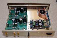
Here is a picture of the copper shield I put in front of the transformer. Although it doesn't look like it from the angle, it stands taller than the transformer - almost all of the way to the top of the chassis. I don't know that it really makes a difference, but I had a spare piece floating around so I used it.
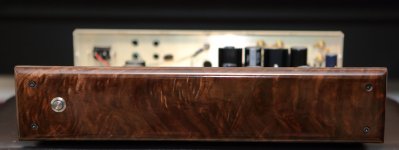
The other image is the walnut front panel with an illuminated power switch. The camera doesn't really capture the way the grain appears to shift when the angle of the light changes. It really looks much nicer in person.
Here is a picture of the copper shield I put in front of the transformer. Although it doesn't look like it from the angle, it stands taller than the transformer - almost all of the way to the top of the chassis. I don't know that it really makes a difference, but I had a spare piece floating around so I used it.
The other image is the walnut front panel with an illuminated power switch. The camera doesn't really capture the way the grain appears to shift when the angle of the light changes. It really looks much nicer in person.
Attachments
- Home
- Amplifiers
- Pass Labs
- Building a Pearl 2